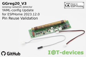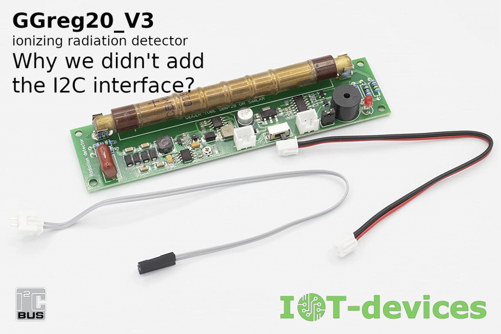
Indeed, why not add such a convenient interface to the module? Here is our next article where we discuss the advantages and disadvantages of equipping the GGreg20_V3 ionizing radiation detector module with an I2C interface.
Note that we really like the I2C serial bus for its simplicity, functionality, and reliability. You can check out our other publications where we look at this great bus:
Як правильно вибрати I2C чіпи. Або про приховану програмну проблему вибору
апаратних модулів / How to choose the right I2C chips. Or the hidden software problem of
choosing hardware modules
Application of I2C bus interface splitter
However, our goal in developing GGreg20_V3 was, and still is, to ensure that our product is as compatible as possible with various systems.
Take a look at this:
(1) If any module or chip has an I2C (or SPI, UART) communication interface, this automatically requires a low-level driver-connector to be written for that device.
(2) Also, such a device cannot be integrated with other components that do not support a specific communication or control interface such as I2C. There are many projects that do not have I2C, or there are not enough free GPIOs for the I2C bus.
(3) The radiation measurement module, under certain conditions, should be capable of being used in the field, without connection to the main controller. The user should be able to use such a device regardless of the conditions in which he finds himself. Without programming or hardware rework.
(4) Equipping the module with an I2C interface requires an embedded controller-companion on the module, which provides data preparation for the consumer and data exchange in Slave Device mode in accordance with the I2C specification. Although it can be a common and inexpensive controller, its presence increases both the price and size of the module. It is also necessary to allocate additional space on the module board for the address selection pads.
(5) A module with an I2C interface requires a main controller and display so that the module can be used for its intended purpose. This is despite the fact that the module already has an embedded controller-companion. The main controllers are very different. Some use Raspberry Pi, or Arduino, and some want to be able to use ESP32/ESP8266. That’s why we don’t put the main controller on the GGreg20 module board. We believe that the user has the right to choose the controller, platform or development environment independently. And our task is to ensure the widest possible compatibility and versatility of our product.
From an electrical point of view, equipping devices in this category with an I2C interface also has no advantages, since both the power and data interface in the I2C variant and the GGreg20_V3 pulse output variant require the same number of signal wires in the loop. Hot-swapping, supported by the I2C bus, is also hardly desirable for this type of module, not to mention the mandatory presence of this function.
In Fig. Here are schematic images of two modules – the current version of GGreg20 without I2C, and the version with I2C interface to show how much you would have to change the module to the actual size (10×10 mm) of the additional chip integrated controller-companion.
Fig. If GGreg20_V3 had an I2C interface (the built-in companion controller providing the I2C Slave Device mode is shown in red))
The only advantages to justify equipping our radiation module with an I2C interface are:
- the ability to connect multiple devices to the I2C interface of the main controller;
- calculation of user values by means of the built-in controller-companion.
But if you carefully weigh the potential benefits and the very specific losses of implementing I2C in a given device, it becomes obvious that it is better to have a universal module with extensive driver support and the ability to use it in “manual” mode than to have a tones of I2C bus advantages that you need to be able to use.
| I2C interface | GPIO pulse counter interface | |
| Autonomous use in “manual” mode | No | Yes |
| Requires a built-in controller-companion | Yes: – higher cost; – larger sizes. | No |
| Driver support | Not available / very limited | The broadest |
| Hardware dependency | High: – main controller; – display. | Low / none |
| User qualification requirements | High: – embed programming .; – administration / config; – interfaces / protocols; – electronics / integration. | Low / none |
In addition to the above, here are two key problems we would like to highlight for potential users. GGreg20_V3 does not have these problems, but they are bound to occur (in some variations) in the radiation measurement module with the I2C interface:
Problem # 1 Field conditions / Emergency situation
Consider this situation: you have a radiation sensor in a drawer waiting for you to finally start programming it, and the next moment you need to leave the house as quickly as possible with one backpack in your hands and, perhaps, start measuring the level of radiation as soon as possible, because a situation of natural or man-made disaster has come, and you are near the epicenter of these events.
We in Ukraine are very familiar with such circumstances, and we take into account the experience accumulated in the most difficult times for the country to make the system design of our products as good as possible.
Our GGreg20_V3 module only needs to be powered by a powerbank (or even a few AA/AAA batteries), or a solar panel and that’s it: you can measure manually by LED flashes and a stopwatch or your own countdown.
The number of flashes per minute, multiplied by the conversion factor, is the radiation level in μSv/h.
The conversion factor for the SBM20 GM-tube is 0.0054. Thus, we have a simple formula:
CPM x 0.0054 = mkSv / hour.
where CPM is the number of flashes per minute ( Counts per Minute ).
For Kyiv[20 – 48] flashes is a normal level (0.10 – 0.26 mkSv / h).
Unlike the GGreg20_V3, a module with an I2C interface will be very difficult to use in the field for its intended purpose. After all, such a module requires a main controller, display, programming tools, software code development and special knowledge and skills to interconnect the required components and program them. This means that the average user without specialist knowledge will not be able to make a measurement with an I2C sensor, even if he happens to have the available tools in his kit.
Problem # 2 Driver support
Even if the surrounding circumstances are fine and the radiation sensor module is operated in a civilization, there are still problems with the design option of the module having an I2C interface. Problems arise for users who want to use their favorite systems / platforms / environments / architectures for IoT development.
There are many systems and user favors, but even the most advanced and popular systems do not have drivers for all the devices that consumers usually buy and try to connect.
Due to the heterogeneity of integration protocols, sometimes you have to write a driver yourself, or wait several years for the system developers to pay attention to this particular commercial device and develop an appropriate driver connector.
Here is a comparison table of common platforms with built-in I2C support for radiation sensors and platforms with GPIO pulse counter support, so that the reader can understand the extent of the problem.
| Platform | Radiation sensor module with I2C, built-in driver platform support | Radiation sensor module with pulse output, built-in driver platform support (GPIO pulse counter, external ISR) |
| Arduino | No | Yes |
| NodeMCU (Lua) | No | Yes |
| MicroPython | No | Yes |
| ESPHome / Home Assistant | No | Yes |
| Espressif ESP-IDF | No | Yes |
| STM32 | No | Yes |
| Tasmota | No | Yes |
This data indicates very eloquently that a sensor with a pulse output, such as the GGreg20_V3, is much easier to connect to any platform, or to use the module stand-alone, if necessary.
Of course, each I2C module usually has its own libraries developed by the manufacturer or by concerned members of the open source software community. For example, the GGreg20_V3 module has several libraries for popular platforms:
| Platform | Link |
| Arduino contributed library | https://www.arduino.cc/reference/en/libraries/ggreg20_v3/ |
| ESPHome / Home Assistant example | https://github.com/iotdevicesdev/ggreg20-v3-homeassistant-esphome-example |
| Tasmota driver example | https://github.com/iotdevicesdev/ggreg20-v3-tasmota-esp32-driver |
| NodeMCU (Lua) example | https://github.com/iotdevicesdev/ggreg20-v3-nodemcu-lua-example |
| NodeMCU (Lua) full functional driver | https://alterstrategy.com/product/radcounter/ |
Note. While every modern IoT platform typically provides I2C bus support, there must also be a driver for each specific hardware module (manufacturer, model, version). Support must be both on the platform side and on the side of the controller to which the module is connected.
Having libraries like the ones in the table is already a good thing. But this does not give any guarantee that these libraries are supported by their authors and are up-to-date, and also that the user will find such a library for his favorite platform and will be able to integrate it and program the end device.
In the case of the pulse counter on the GPIO, the situation is completely different: all platforms support this function and are very easy to program.
In lieu of conclusion.
Despite the obvious advantages of the I2C bus, if in the future we decide to add I2C support to the GGreg20 module, it will be another, alternative device with these capabilities. And consumers will be able to choose which option suits them best.
Buy a GGreg20_V3 ionizing radiation detector with pulse output.
We wish you success!