Everyone who is involved in DIY IoT projects is familiar with the LM75 temperature sensor. Termometer LM75 – it is a cheap and convenient sensor that has sufficient accuracy and measurement range.
But its main advantage is that it works via the I2C bus.
Why these thermometers are underrated
Someone may say that LM75 is not the best sensor in terms of its technological features and design as a chip. Indeed, there are many other types of temperature sensors, such as 1-Wire Dallas DS18b20. These sensors have a one-wire connection and many other design advantages, such as waterproof metallized capsule-shaped housings, etc. It is possible to connect many thermometers to the 1-Wire bus on a single wire, 1-Wire supports error detection and device identification, etc.
But the 1-Wire bus has one and the most important drawback – there are no other devices for this bus except thermometers. That’s not exactly true, they are produced, but it’s such an unpopular segment that they are impossible to buy.
When we need to build a device of medium complexity, such as a weather station, several different sensors and other peripherals need to be connected to the main controller (a list, for example):
- BME680 / BME280 I2C / SPI;
- DS18b20 1-Wire;
- SPI / I2C display;
- Lightning sensor AS3935 SPI / I2C;
- Light sensor MAX44009 I2C;
- Temperature and humidity HDC1080 I2C;
- CCS811 I2C sensor;
- SCD4X I2C sensor.
And even with the powerful ESP32 (not to mention the ESP8266 and similar controllers, such as Arduino or RPI Pico W), we will have to solve the problem of optimizing the number of interfaces and protocols. After all, the processing of several different protocols will sooner or later affect our development and will require simplification not only on the hardware side (budget of free I/O ports), but also the software implementation of drivers for different protocols and interfaces that must run in parallel in the main loop of the controller.
Note. We are not writing about SPI here, because it is a specialized protocol with a completely different purpose and strengths that apply only to exceptional situations when it comes to sensors.
Therefore, in our opinion, you should choose solutions that can be easily expanded and operated in the future. 1-Wire and SPI devices are not well suited for such requirements and therefore we recommend not considering them unless it is absolutely necessary (as in the SPI case for high-resolution displays or measuring values at near real-time speeds).
It is worth trying to build an optimal hardware and software solution – we take a step towards the I2C bus. That is, since we will have an SSD1306 display with I2C on the main controller, an I2CUI4_V1 keypad with I2C, why would we need to install temperature sensors with any other interface? – So we decided to use only the I2C bus. All connections will be made through the I2CHUB_V1, splitter/hub, which supports the connection of 5 devices to the controller at the same time.
Note. As a reminder, I2C is a great bus – it not only allows you to connect many devices simultaneously, but also provides the ability to identify devices on the bus, control erroneous data, and hot-swap (connect and disconnect devices by the user on the go).
Built-in drivers in ESPHome
However, when we search on the ESPHome website, it turns out that the LM75 sensor, which we were going to use in the project as a thermometer, is not supported – there is no built-in driver.
We begin to do our own little investigation into the available drivers in ESPHome for temperature sensors like the LM75 ($0.89 USD on Mouser). And we find out that there are two other thermometers for which a built-in driver is already written in ESPHome:
Both sensors would have suited us technically. They are available on Mouser and other similar platforms. But we could not find ready-made modules with these chips at a price that would be close to the price of modules with LM75.
We thought that this was not acceptable to us, as it would not be to most of our readers. Given the similarity of these chips, no one wants to overpay 5-10 times for a thermometer module if you can buy an LM75-based module in every store.
Interestingly, the TMP1075 sensor is compatible with the LM75 specification (this is clearly stated in the datasheet), which is de facto the industry standard. Therefore, we concluded that we could try to connect our LM75 thermometer with the drivers for TM1075 that are built into ESPHome.
Unfortunately, we failed to make such a connection, even though the addressing on the bus and the internal registers are identical for the mentioned sensors. The only difference is that the TMP1075 also has a special identification register, which the LM75 sensor does not have. But even attempts to make changes to the sensor type checking at the CPP-code level of this driver did not allow us to use it with the LM75 chip.
Note. To be honest, we still don’t understand why the developers and contributors of ESPHome haven’t made a built-in driver for the LM75 yet. We wouldn’t have to write this article and spend a lot of time doing strange experiments.
So we went back to the starting point and did what we should have done from the very beginning.
Connecting the driver externally
As you probably know, ESPHome has at least two mechanisms for connecting custom device drivers from the outside: Custom Component and External Component.
Custom component is currently considered an obsolete integration option and is not recommended by the ESPHome documentation.
Instead, the documentation recommends using another, alternative way, which in our opinion is currently the only, easiest and best way to perform driver integration yourself – External Component.
The difference of the External Component is that the ESPHome user does not manually write interfaces for data flows from the sensor through low-code roundabouts, but uses fully defined mechanisms, which, by the way, are also used by all other ESPHome components:
So, to connect an External Component, you first need to describe its mapping correctly. We won’t dive into the details of programming and configurations here, because we found a ready-made component for the LM75 on GitHub.
To add LM75 sensors, you only need to add a few lines to the YAML configuration of the device in ESPHome:
- connect an external component (External Component):

- add LM75 sensor entities:
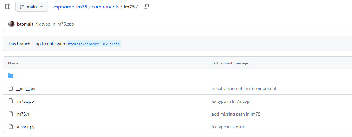
For convenience, we have forked the esphome-lm75 repository provided by https://github.com/btomala on GitHub to our account https://github.com/iotdevicesdev/esphome-lm75
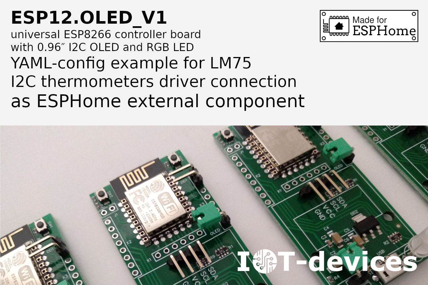
An example of how the connection of LM75 drivers for the ESP12.OLED_V1 controller manufactured by IoT-devices, LLC looks like in ESPHome:
# YAML Config Example
esphome:
name: esp12oled-lm75
friendly_name: esp12oled-lm75
comment: "Configuration example of two LM75 for ESP12.OLED_V1 with ESPHome firmware"
project:
name: "iot-devices.esp12oled-lm75"
version: "1.0.0"
external_components:
- source: github://iotdevicesdev/esphome-lm75
components: [ lm75 ]
esp8266:
board: nodemcuv2
logger:
api:
encryption:
key: "8tDDLc3S5dnSjADItGR5+7KxoUBhUIqeOiJZIXy"
ota:
password: "c15e9a44e1408352d945b8cd35b79"
wifi:
ssid: !secret wifi_ssid
password: !secret wifi_password
ap:
ssid: "Test-Node Fallback Hotspot"
password: "rtF1XxDZ9"
captive_portal:
i2c:
sda: 4
scl: 5
id: i2c_bus
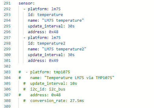
sensor:
- platform: lm75
id: temperature
name: "LM75 temperature"
update_interval: 30s
address: 0x48
- platform: lm75
id: temperature2
name: "LM75 temperature2"
update_interval: 30s
address: 0x49
# END YAML Config Example
Note. This code is also available on our GitHub: github.com/iotdevicesdev/ESP12.OLED_V1-LM75-ESPHome
Project components
1 x ESP12.OLED_V1 module with ESPHome 2023.12.5 firmware;
1 x I2CHUB_V1 module:
1 x LM75 module (no brand);
1 x CJMCU-75 module.
Project results
This is the main thing we wanted to tell you in this text:
- We have connected the LM75 via the External Component mechanism so easily and simply that we could not believe it ourselves after some complicated experiments with the TMP1075 driver.
- The dependencies are pulled directly from GitHub, or can be linked from a local repository on your ESPHome/HomeAssistant drive. The External Component connected in this way is automatically included in the firmware during its compilation.
- We have verified that there are no problems with addressing multiple LM75 sensors simultaneously with this component.
- It’s as simple as connecting a sensor with a built-in driver like BME280 to ESPHome. The simplicity of using an off-the-shelf component via the External Component method is nothing compared to using the obsolete Custom Component method that we used to do for our other applications with the VEML6070 UV sensor.
As you can see in the following screenshots, our project has been successfully completed:
- LM75 is connected to the ESP12.OLED_V1 controller with ESPHome firmware;
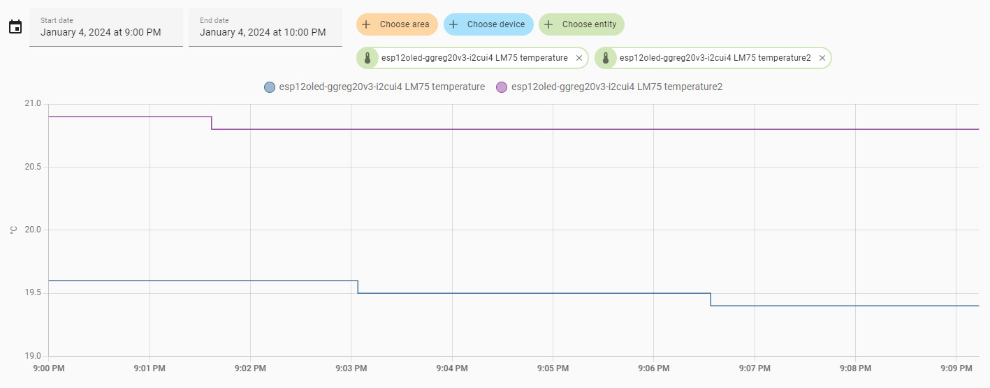
- Two LM75 sensors work simultaneously with the main controller. Where two sensors work, eight can work (if necessary, the LM75 has three I2C address pins, which allows you to work with eight sensors on each I2C bus at the same time);
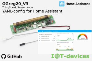
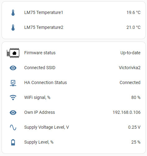
- The data from the sensors is sent to Home Assistant and displayed on the Dashboard;
- Further, the sensor values can either be displayed independently on the ESP12.OLED_V1 controller display using the ESPHome firmware, and/or can be used in Home Assistant automation scenarios.
LM75 sensor values on the Home Assistant server Dashboard:
Graphs from the Home Assistant server’s Logbook:
LM75 sensor values in the Developer Tools menu of the Home Assistant server:
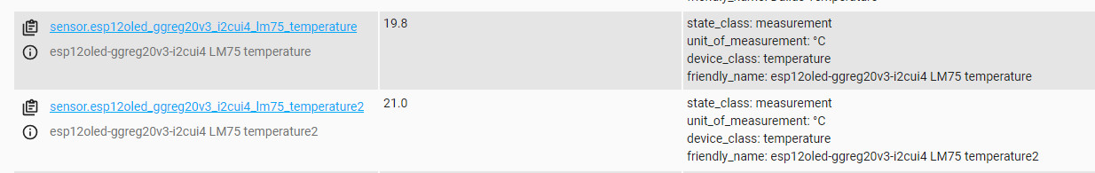
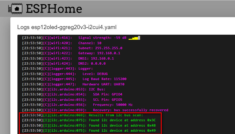
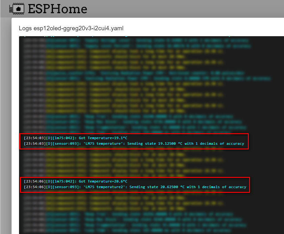
Screenshots of the ESPHome console:
- Devices found during I2C bus scan (display and two thermometers)
- Drivers for LM75 sensors initialized

- ESPHome receives sensor data and transmits it to Home Assistant
That’s all we have planned to discuss on this topic for now.
Thank you for your attention!
Good luck!