The I2CHUB_V1 module – an I2C bus interfaces splitter
259грн.
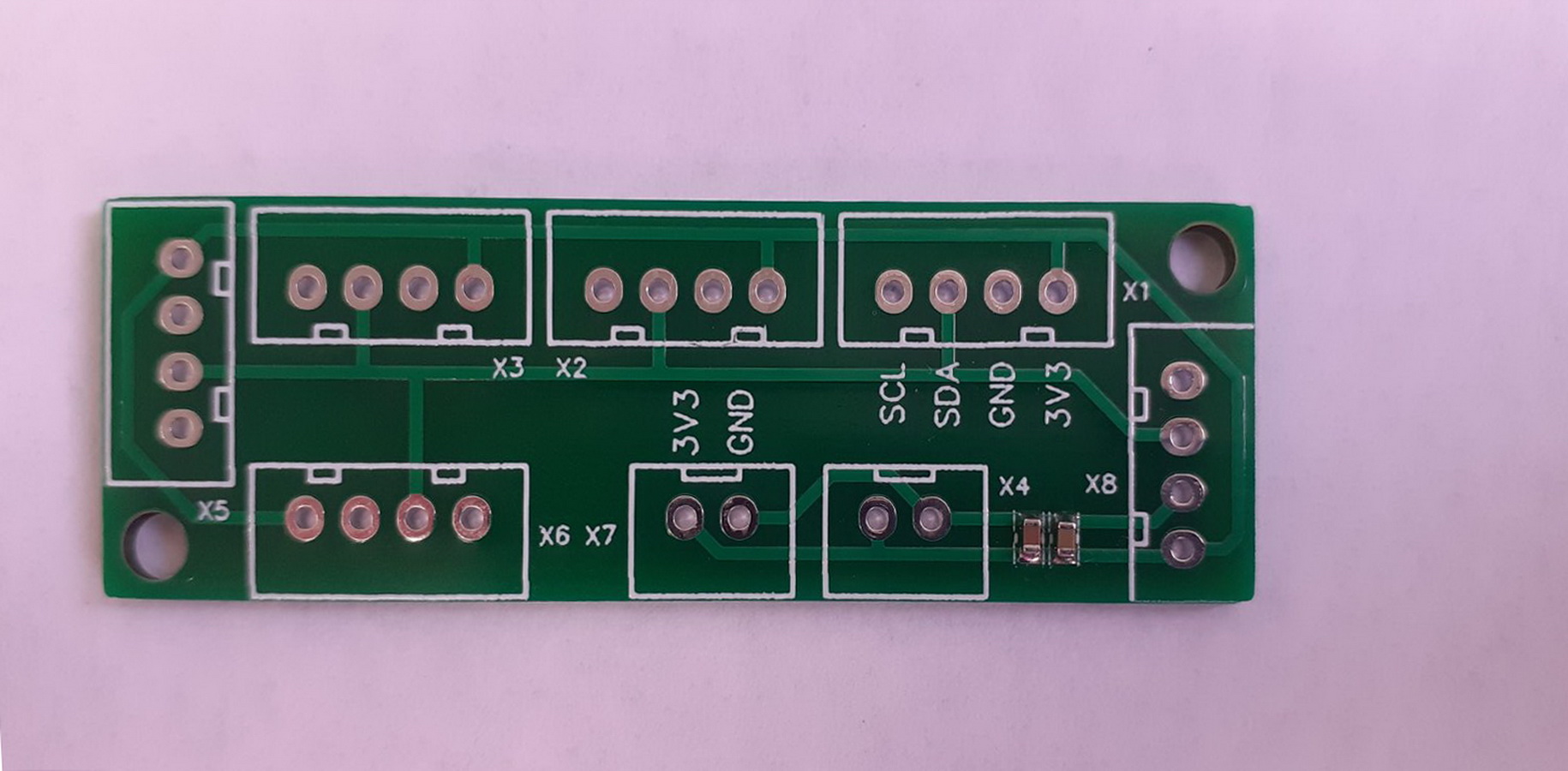
The offered device I2CHUB_V1 – splitter and converter of interface connector types in one module.
The I2CHUB module will be useful for:
- Creating prototypes of electronic devices with a large number of connected modules via the I2C bus, which, traditionally for Arduino, are connected to the system by cables with pin connectors from Dupont, JST, or others with a pin-to-pin step of 2.54 mm;.
- Construction of DIY devices with a large number of modules connected by the I2C bus;
- Remotely distanced groups of modules or devices, such as weather stations with remote cable groups of sensors.
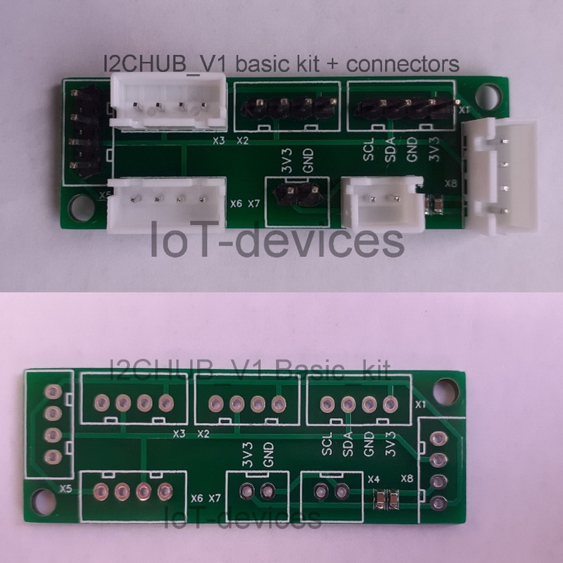
On the module, as one of the delivery options of the User’s choice, it is possible to install six connectors (4 pins 2.54) with I2C interface and two connectors (2 pins 2.54) for the power supply. The User can also add the required number of appropriate interface cables to the kit when ordering.
Description
Purpose
System digital serial bus I2C due to the simplicity, high enough speed, and reliability of data transmission over relatively long distances – has a high rating of use in industrial components, modules and devices, and DIY projects.
The I2C bus also allows hot connection/disconnection of slave devices and identification of devices by addresses, or unique internal register data. The bus topology and at least 7-bit addressing allow up to a hundred slave devices to be connected to the I2C network simultaneously.
All this allows to build a convenient, reliable, and functional infrastructure of sensors and actuators around the main controller.
The main controller, however, usually has only one I2C interface and/or a limited number of free pins. That is why, in order to fully use the I2C bus in the development and operation, interface splitters are used. And then through the splitter connect to the main controller the required number of sub-components.
The offered device is specially designed for such tasks – I2CHUB_V1 – splitter and converter of interface connector types in one module.
The I2CHUB module will be useful for:
- Creating prototypes of electronic devices with a large number of connected modules via the I2C bus, which, traditionally for Arduino, are connected to the system by cables with pin connectors from Dupont, JST, or others with a pin-to-pin step of 2.54 mm;.
- Construction of DIY devices with a large number of modules connected by the I2C bus;
- Remotely distanced groups of modules or devices, such as weather stations with remote cable groups of sensors.
On the module, as one of the delivery options of the User’s choice, it is possible to install six connectors (4 pins 2.54) with I2C interface and two connectors (2 pins 2.54) for the power supply. The User can also add the required number of appropriate interface cables to the kit when ordering.
Description
The I2CHUB interface splitter module is a passive device and allows you to connect several (up to five) devices (sensors or actuators) to the main controller at the same time. The controller and splitter form a network of connected I2C devices with a bus-type topology and Master-Slave interaction profile.
Also, if you install different connectors (JST and/or Dupont) on the board of the splitter module, I2CHUB will also act as a converter of physical interfaces, which is very convenient for prototyping and development.
Multiple I2CHUB devices can be freely cascaded within the limits allowed by the I2C bus specification, and further, expand the total number of free ports in the network of subordinate smart devices of the master controller.
Connection
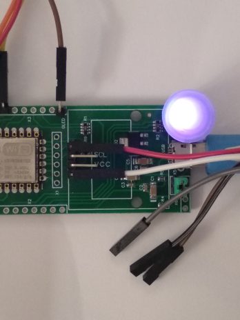
The main controller which will work in the “Master mode” is connected to one of the 4-pin ports of the module. Subordinate devices are connected to other 4-pin ports. In this scheme, all devices are powered by the main controller, and the 2-pin power connectors on the I2CHUB module board are not involved.
Power connectors can only be used if each of the devices on the bus is powered from its own source.
For example, the main controller can feed only itself and then only the interface signals are connected to the splitter: SDA, SCL, GND – without power, but with a common “ground” signal for all devices on the bus.
In this case, slave devices connected to the I2CHUB splitter must be powered directly from it:
- power to the I2CHUB is supplied via two-pin connectors;
- power from the I2CHUB to each device is supplied through the appropriate 4-pin interfaces;
- keep in mind that the controller is powered by itself.
WARNING! Be careful when designing – do not allow the current to run on the bus from multiple power sources – the devices on the bus will be damaged under the counter-current impact.
If you want to use an additional I2CHUB splitter, then instead of one of the slave devices you may connect an additional splitter, and then connect to it other devices that do not have enough free ports on the first splitter.
Recipe application as an example
To build a personal weather station, it is necessary to connect a number of sensors to the controller to measure ionizing radiation, ultraviolet light, temperature, atmospheric pressure, relative humidity, and to detect lightning strikes.
The Bill of Materials, in this case, it is possible to make as the following:
- MSU: ESP12.OLED module based on ESP8266 and OLED SSD1306, I2C;
- I2C Splitter: I2CHUB 1-to-5 I2C bus passive hub;
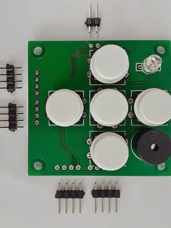
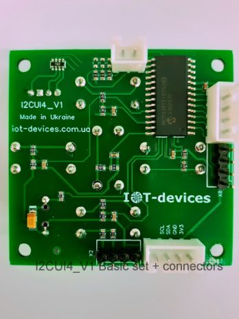
- user interface module: I2CUI4_V1, I2C;
- ionizing radiation sensor: GGreg20_V3, discrete pulse output;
- ultraviolet sensor: VEML6075, I2C;
- CO2 sensor: CCS811, eCO2 & eTVOC, I2C;
- temperature, atmospheric pressure, humidity sensor: BME280, I2C;
- Lightning detector: AS3935, I2C.
As we can see in this example, with a fairly wide functionality of the weather station, only one I2CHUB splitter will be enough to connect via I2C bus all the sensors listed to the main controller.
Moreover, if it is necessary to expand the weather station with new sensors (for example, add a light sensor: MAX44009, I2C), it will be easy to do just by using one more splitter. In this scenario, we get 4 more free I2C ports.
Product delivery kits.
-
Basic Kit:
- I2CHUB_V1 module board without connectors.
Note: The user can install his own 2.54 mm connectors on such a board
Technical description: i2chub_v1-product-description-and-datasheet-ukr, i2chub_v1-product-description-and-datasheet-eng.
Dimensions
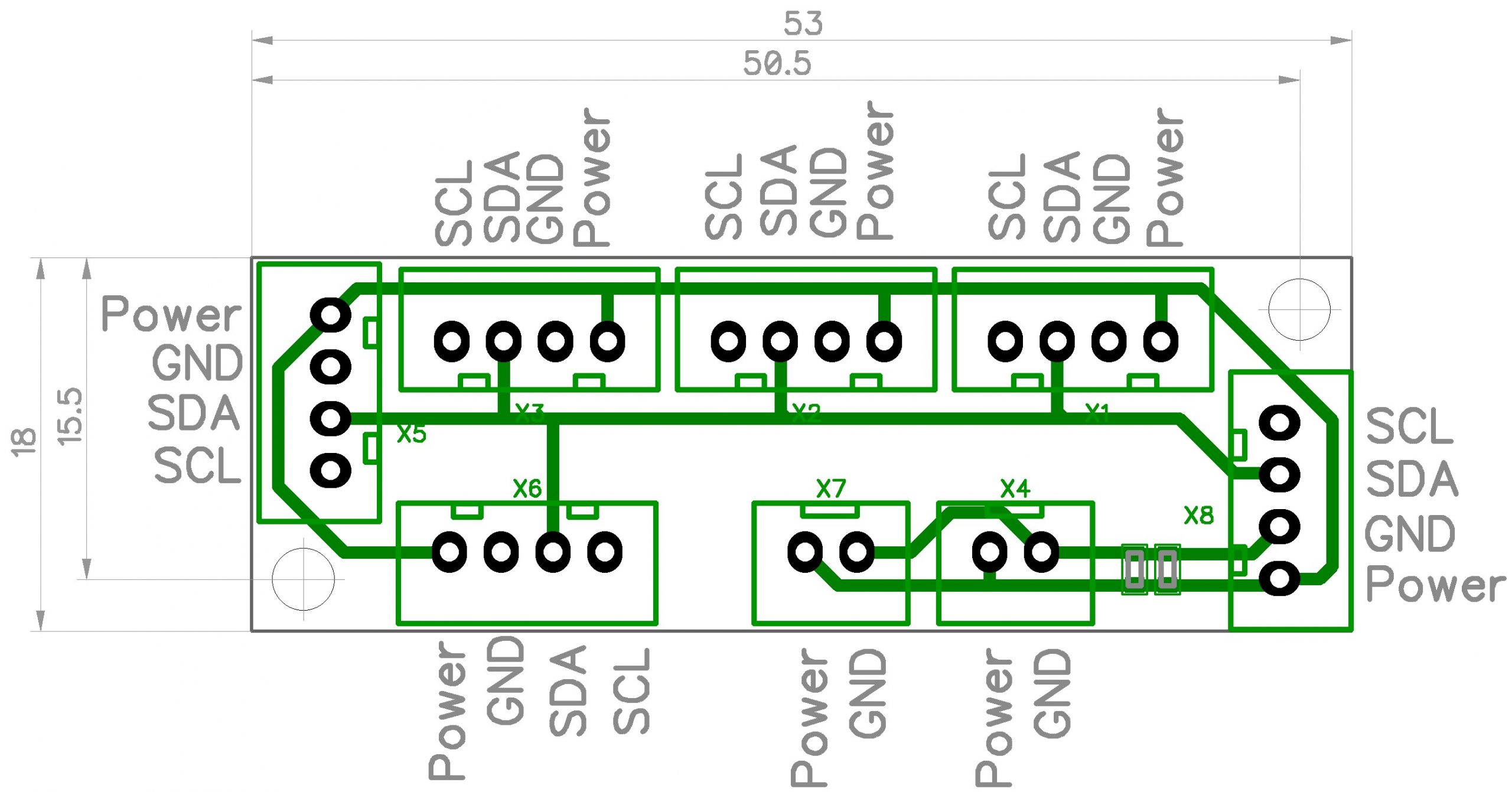
The module board has the following linear dimensions:
- X: 53 mm;
- Y: 18 mm;
- Z:< 15 mm with connectors.
Dimensions along the axes of the mounting holes:
- X: 48 mm;
- Y: 12 mm.
- Holes: 2 x d3 mm.
References
| Manufacturer site | https://iot-devices.com.ua |
| Shop on Tindie for international orders | https://www.tindie.com/stores/iotdev/ |
| Shop for local orders within Ukraine | https://iot-devices.com.ua/shop/ |
| Facebook page | https://www.facebook.com/IoT-devices-114746816966582 |
| https://twitter.com/iotdevicescomua | |
| YouTube | https://www.youtube.com/channel/UCHpPOVVlbbdtYtvLUDt1NZw |
| info@iot-devices.com.ua |
Manufacturer message
Dear Reader! Thank you for your interest in our products. We hope that you enjoy this device. IoT-devices was born thanks to the support of our customers and thanks to our experience and love for Electronics.
Designed and made by IoT-devices with freedom & wisdom in Ukraine – 2021. All rights reserved.
Only logged in customers who have purchased this product may leave a review.


Reviews
There are no reviews yet.