Testing the emulator
After we’ve built the emulator and programmed the ESP8266, we can test it to make sure it’s working correctly.
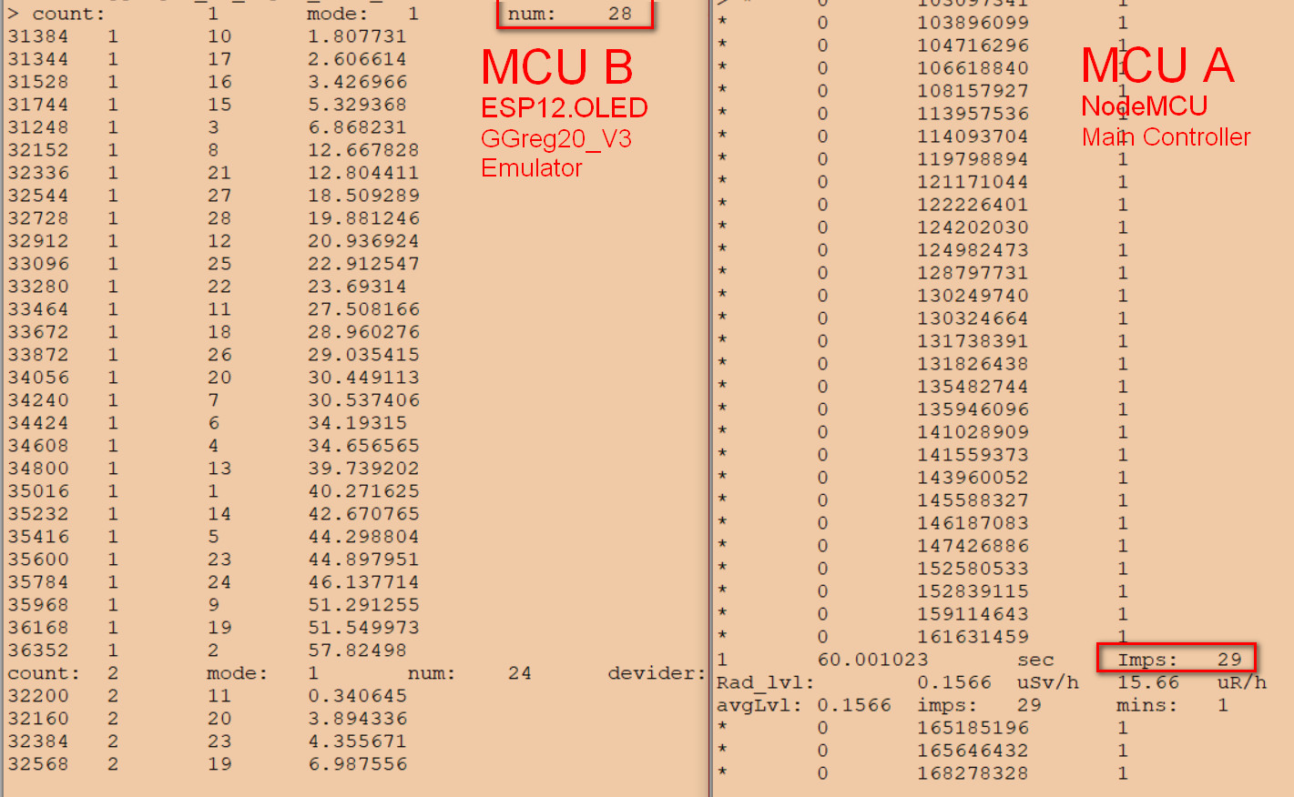
Having made the physical diagram and developed and loaded/compiled the Lua code into the controllers, we run the emulator and the main controller to check how our testbed works.
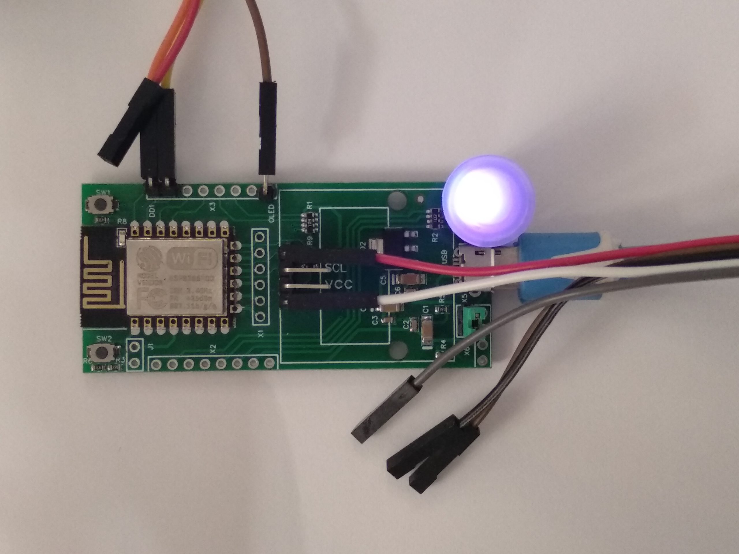
As you can see, the connection of the emulator is very simple: the micro USB power cable and the pulse output signal wires, and you can also connect the debug console via UART if desired.
The following screenshots show the diagnostic data and their measurements. We also show an example of event distribution at the emulator output, that we built to clearly show how the random number generator of the ESP8266 controller works according to our proposed implementation via timers.
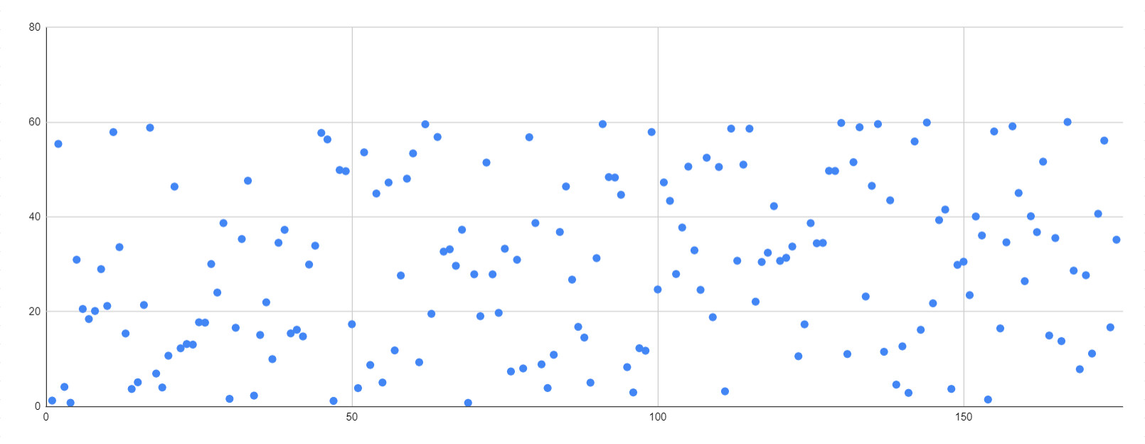
As we can see, the events that the emulator generates at the output are chaotic, that is, they have a character where a cursory examination does not show a certain graphical pattern.
Here is another graph of a test set of 175 events per minute, but in a slightly different format. Note the horizontal axis. The value of the initial sequence numbers of events in the loop are arranged chaotically on this graph, as they happened in reality at the output of the emulator:
Of course, the verification of true randomness of events is not the goal of this publication and is far beyond its scope. We simply rely on the thesis that the ESP8266 has a hardware true random number generator.
Known limitations
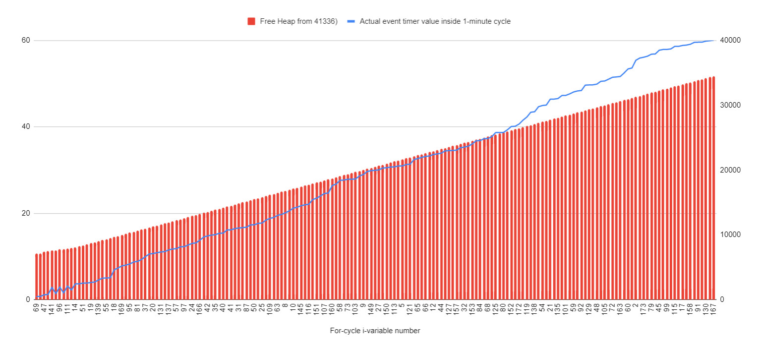
Among the known limitations of this method of creating a Geiger counter emulator is the memory size of the ESP826 controller, in which we create in a loop the required number of one-shot timers with random times of firing. Each timer, in fact, is a function that takes a certain amount of RAM.
When the timers are fired, the memory is immediately released. The execution of the code we developed resembles a spring, which in a cycle once a minute is sharply compressed and slowly uncompressed within the available memory of the controller.
Thus, the maximum possible number of events generated by our chosen method of generating random events at the emulator output directly depends on the amount of free RAM and the speed of the controller.
Experimentally we found that ESP8266 with NodeMCU firmware and Lua language can confidently generate about 260 events per minute. This is more than enough pulses per minute for the emulator project and the radiation levels it supposedly registers.
That is all we planned to tell you about. Now you know our version of how you can make your own Geiger counter emulator, as well as what and who can benefit from such a device. However, if you want to buy a ready-made emulator, you can do it on our website or on Tindie.
Site IoT-devices.com.ua: GCcemu20_V1
tindie.com: GCcemu20_V1
Overall, building a Geiger counter module emulator can be a fun and educational project. It allows you to simulate the readings of a Geiger counter module without the need for radioactive sources. We hope this guide has been helpful, and we encourage you to experiment with different components and programming techniques to customize your emulator further.
The beginning of the article:
Geiger counter emulator of GGreg20_V3 module by means of ESP8266 Part 1: Introduction and Overview
Geiger counter emulator of GGreg20_V3 module by means of ESP8266 Part 2 Building the Emulator
Good luck!
IoT-devices LLC Team.