Geiger counter emulator: what we need
To build the Geiger counter module emulator, we’ll need the following parts and materials:
- ESP8266 #1 as the main one (MCU_A, NodeMCU module);
- ESP8266 #2 as GGreg20_V3 emulator (MCU_B, ESP12.OLED module);
- Jumper wires;
- USB cable for programming and power.
Next, we’ll need to program the main controller MCU_A and emulation software script code GGreg20_V3 for MCU_B.
Note 3. We will give examples in this publication with our own ESP12.OLED modules. However, if you do not have an ESP12.OLED module, you can also use an ESP8266-based development board such as the NodeMCU and develop the software yourself, following the examples in the text. If you wish to use an off-the-shelf device please read the rest of this article because we have provided a link to our ready-to-use emulator module which you can buy further on.
Note 4. In this, as in other publications, we will give examples using the simple and powerful Lua scripting language available in the popular NodeMCU firmware.
The budget of the inputs/outputs we need
On the main layout controller, we must define the input/output ports that will perform the task of recording input pulses from the Geiger counter emulator module.
On the Geiger counter emulator module we need a bit more ports. Here we need I/O ports: for emulation of output pulses, for RGB LED and for the switch button of the emulator operation mode.
| MCU_A role (Main Contr.) | MCU_B role (GC emulator) | |
| 1 х GPIO of input pulse counter | NodeMCU | – |
| 1 х GGreg20_V3 output emulation GPIO | – | ESP12.OLED |
| 3 х RGB LED GPIO for GGreg20_V3 output pulses indication | – | ESP12.OLED |
| 1х GPIO of the emulator mode switch button | – | ESP12.OLED |
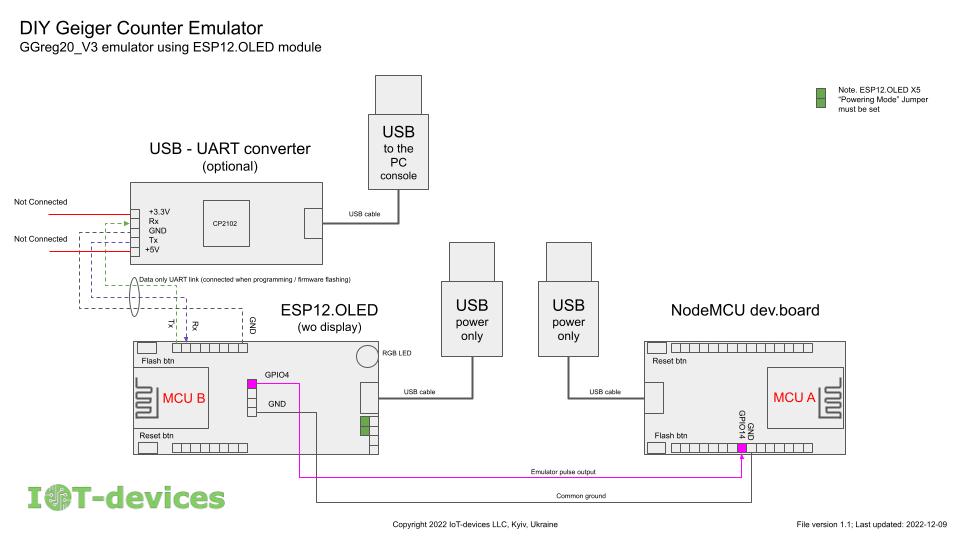
Wiring diagram
To make the interaction between the main controller and the GGreg20_V3 module emulator look realistic, we suggest taking advantage of the built-in properties of some I/O ports of the ESP12.OLED board and select the following GPIOs on the MCU_B emulator controller:
- we recommend using GPIO4/D2 (GPIO D-index in Lua) to emulate the pulse output of GGreg20_V3;
- we can use the Flash button (GPIO0/D3) built into the ESP12.OLED board to switch the emulator operation modes;
- the built-in RGB LED on the ESP12.OLED module takes GPIO14/D5; GPIO12/D6; GPIO13/D7;
On the main module of the MCU_A controller we propose to select the following port for the input pulse counter:
- GPIO14 / D5.
Note 5. We recommend the following materials as background information on port numbering:
The standard for planning and applying pins was developed by alterstrategy.lab: https://alterstrategy.com/recommended-pin-use-standard/
NodeMCU firmware documentation: https://nodemcu.readthedocs.io/en/latest/modules/gpio/
Documentation for the ESP12.OLED module is on the website: https://iot-devices.com.ua/en/product/esp12oled-universal-esp8266-mcuboard-oled-en/
and on Tindie: https://www.tindie.com/products/iotdev/esp12oled-universal-esp8266096oled-mcu-board/
Let’s update the table with the specific I/O ports we selected:
| MCU_A role | MCU_B role | |
| 1 х GPIO of input pulse counter | NodeMCU GPIO14/ D5 | – |
| 1 х GGreg20_V3 output emulation GPIO | – | ESP12.OLED GPIO4 / D2 |
| 3 х RGB LED GPIO for GGreg20_V3 output pulses indication | – | ESP12.OLED GPIO14 / D5 GPIO12 / D6 GPIO13 / D7 |
| 1х GPIO of the emulator mode switch button | – | ESP12.OLED GPIO0 / D3 |
Emulator operating modes
In order for our GGreg20_V3 emulator to be able to simulate operation under conditions of different radiation levels, we propose to implement the possibility to switch the radiation power range, which is as if measured by the device and fed to the pulse output.
By pressing the Flash button (D3), the user can alternately switch modes to select the desired one.
To make the emulator easy to use, the ESP12.OLED’s RGB LED flashes in different colors that can be easily distinguished by the human eye. Each emulator operating mode has its own color assigned to it. Therefore, when the emulator gives the pulse output a signal about a simulated detection the LED will also blink in the color of the current mode of operation.
Radiation level ranges
We propose to implement the emulation of the following ranges of ambient radiation, which MCU_B will simulate:
Mode 0. No pulses (sensor error simulation);
Mode 1. Natural background radiation: 0.1 – 0.2 µSv/h;
Mode 2. Acceptable level: 0.2 – 0.3 µSv/h;
Mode 3. Increased level: 0.3 – 0.6 µSv/hour;
Mode 4. Dangerous level: 0.6 µSv/hour – 1.5 µSv/hour.
By default, the module will start after applying power, from “Mode 1”. We chose this mode as the initial one only because it is convenient when, after applying power, we immediately receive pulses at the level of background radiation.
The real GGreg20_V3 module is equipped with a Soviet-made SBM-20 Geiger tube. This tube has the following conversion factor of pulses per minute to microsieverts per hour:
μSv per hour = CPM * 0.0057
Let’s perform the reverse operation to calculate for the radiation ranges the appropriate number of pulses per hour that the emulator would have to generate while operating in a certain mode:
CPM = μSv per hour/ 0.0057
We make a rough calculation so as to form power ranges which do not overlap in value:
Mode 0. 0 CPM;
Mode 1. 18 CPM to 35 CPM;
Mode 2. 36 CPM to 52 CPM;
Mode 3. 53 CPM to 105 CPM;
Mode 4. від 106 CPM до 264 CPM.
The correlation of the color of the RGB LED flashes to a certain mode of operation is as follows:
| Operation mode | Flash color | R | G | B |
| Mode 0 | no flashes black | 0 | 0 | 0 |
| Mode 1 | cyan | 0 | 1 | 1 |
| Mode 2 | green | 0 | 1 | 0 |
| Mode 3 | red | 1 | 0 | 0 |
| Mode 4 | magenta | 1 | 0 | 1 |
Now we have to write the appropriate Lua-code for the MCU_A role and for the MCU_B role.
Example. Geiger counter code for the main controller (MCU_A role)
We take this code from GitHub here:
https://github.com/iotdevicesdev/ggreg20-v3-nodemcu-lua-example
The code from GitHub is completely ready to use. To run the code, you need to download it from the Internet and upload it to the controller, for example to the NodeMCU module, as in our case. You also need to write another Lua-script and load it into the controller as well:
-- filename: mcu_a.lua
-- MCU_A Lua code example
-- Copyright 2022 IoT-devices LLC, Kyiv, Ukraine
dofile('ggreg20_v3_nodemcu_firmware_lua_example.lua')
init(5, 1, 60000)

function snsrUpd()
ma5_rad_lvl, cpm, minutes = read()
print(ma5_rad_lvl, cpm, minutes)
end

snsrUpd_tmr = tmr.create()
snsrUpd_tmr:register(60000, tmr.ALARM_AUTO, function() snsrUpd() end)
snsrUpd_tmr:start()Example. Code for the GGreg20_V3 module emulator (MCU_B role)
The Lua documentation tells us that in high-speed tasks we need to reassign global identifiers to local identifiers, which increases execution speed by a factor of ten. Therefore, we will do it as follows:
local gpio = gpio
local mode = gpio.mode
local trig = gpio.trig
local write = gpio.write
local read = gpio.read
local INT = gpio.INT
local OUTPUT = gpio.OUTPUT
local FLOAT = gpio.FLOAT
local HIGH = gpio.HIGH
local LOW = gpio.LOW
local PULLUP = gpio.PULLUP
local print = print

local tmr = tmr
local create = tmr.create
local now = tmr.now
local delay = tmr.delay
local alarm = tmr.alarm
local ALARM_SINGLE = tmr.ALARM_SINGLE
local ALARM_SEMI = tmr.ALARM_SEMI
local ALARM_AUTO = tmr.ALARM_AUTO
local register = tmr.register
local start = tmr.start
local stop = tmr.stop

local node = node
local heap = node.heap
local random = node.random
We also need to configure the GPIOs that will be responsible for their functions (see above):
mode(3,INT,FLOAT)
mode(4,OUTPUT, PULLUP)
write(4, HIGH)
To generate pulses that simulate the output interface of GGreg20_V3, we need to randomly run the following function:
local function pulseOut()
	write(4, LOW)
	delay(10)
	write(4, HIGH)
end
But in order to fully emulate the Geiger counter, it is not enough to just run pulseOut() a certain number of times per minute. In fact it is more complicated and we need to runpulseOut(), in such a way that the real randomness of the appearance of pulses on the ESP8266 output is performed.
Given the extensive capabilities of the platform, we could even suggest several ways to implement this functionality, but we will limit ourselves to one of them, the one that, in our opinion, reproduces the pulse randomness of the real Geiger counter module as much as possible.
To do that we need to use a random number generator, which, according to the NodeMCU firmware documentation, is capable of generating real random numbers. The firmware has a ready-made method node.random() for this purpose. node.random().
To distribute a chosen number of pulses chaotically for one minute, we will use timers, which can be created in a theoretically unlimited number:
create():alarm(timer timeout, timer type, callback function)The only limitation is the amount of free RAM of the controller. Experimentally, we found that we can easily create about 260 pulses per minute in this way, which fits into our requirements for the maximum level of virtual radiation that our emulator can reproduce.
Thus, the function that creates randompulseOut(), start timeouts in the loop looks like this
local t_start = 0
local count = 0
local function randGen(pulses)
	for i = 1, pulses do -- pulses
			create():alarm(random(60000), ALARM_SINGLE,
				function()
						print(heap(), count, i, (now() - t_start)/1000000)
						pulseOut()
				end
			)
	end
end
Working together, our developed functions randGen(pulses) and pulseOut() create on the ESP8266 output the necessary number of absolutely random pulses of 10 microseconds each per one minute.
We set the number of pulses per minute with the parameter pulses.
In order for the emulator to work in different power modes of simulated radiation it is necessary to provide a random value of the number of impulses pulses, falling as a task at the input of the randGen() function randGen(). . This can be done as follows:
radMode = 1
rand_tmr = create()
rand_tmr:register(1000, ALARM_AUTO,
	function()
		if radMode == 0 and running == 0 then
			print(heap(), 'Mode0:Snsr Err emu')
			return 0
		end
		local num = 0
		if radMode == 1 then
			num = random(math.ceil(18),math.ceil(35))
		elseif radMode == 2 then
			num = random(math.ceil(36),math.ceil(52))
		elseif radMode == 3 then
			num = random(math.ceil(53),math.ceil(105))
		elseif radMode == 4 then
			num = random(math.ceil(106),math.ceil(264))
		end
		if num ~= 0 then print('count:',count + 1,'mode:',radMode, 'num:',num); randGen(num) end
	end
)

rand_tmr:start()
By setting the value of the global variable radMode, the user can specify one of five modes of ionizing radiation power reproduced at the emulator output.
The last thing we need to provide in the emulator is to switch the radiation power mode using the built-in Flash/GPIO0/D3 button:
trig(3, 'down',
	function(lvl, ts, cnt)
		if radMode < 4 then radMode = radMode + 1 else radMode = 0 end
		print ('New radMode:', radMode)
	end
)
Full emulator software code
We don’t have a ready-made example for this controller role, as was the case with the main controller (MCU_A). So we will write the necessary code from scratch. Here is the minimum required code capable of emulating Geiger counter pulses.
Note 6. The code in this section is an example. You can download and set up this example yourself in your own Geiger counter emulator, or purchase a ready-to-use hardware module with firmware and fully functional software from our shop or Tindie at the following links:
IoT-devices.com.ua: GCcemu20_V1
Tindie: GCcemu20_V1
Warning! This example code has its own limitations and differs significantly from the code we have developed for commercial use and sell as part of the emulator product on our website and other commercial sites.
-- filename: mcu_b.lua
-- MCU_B Lua code example
-- Copyright 2022 IoT-devices LLC, Kyiv, Ukraine
local t_start = 0
local count = 0
radMode = 0

local gpio = gpio
local mode = gpio.mode
local trig = gpio.trig
local write = gpio.write
local read = gpio.read
local INT = gpio.INT
local OUTPUT = gpio.OUTPUT
local FLOAT = gpio.FLOAT
local HIGH = gpio.HIGH
local LOW = gpio.LOW
local PULLUP = gpio.PULLUP
local print = print

local tmr = tmr
local create = tmr.create
local now = tmr.now
local delay = tmr.delay
local alarm = tmr.alarm
local ALARM_SINGLE = tmr.ALARM_SINGLE
local ALARM_SEMI = tmr.ALARM_SEMI
local ALARM_AUTO = tmr.ALARM_AUTO
local register = tmr.register
local start = tmr.start
local stop = tmr.stop

local node = node
local heap = node.heap
local random = node.random

mode(3,INT,FLOAT)
mode(4,OUTPUT, PULLUP)
write(4, HIGH)

local function pulseOut()
	write(4, LOW)
	delay(10)
	write(4, HIGH)
end

local function randGen(pulses)
	for i = 1, pulses do -- pulses
			create():alarm(random(60000), ALARM_SINGLE,
				function()
						print(heap(), count, i, (now() - t_start)/1000000)
						pulseOut()
				end
			)
	end
end

rand_tmr = create()
rand_tmr:register(1000, ALARM_AUTO,
	function()
		if radMode == 0 and running == 0 then
			print(heap(), 'Mode0:Snsr Err emu')
			return 0
		end
		local num = 0
		if radMode == 1 then
			num = random(math.ceil(18),math.ceil(35))
		elseif radMode == 2 then
			num = random(math.ceil(36),math.ceil(52))
		elseif radMode == 3 then
			num = random(math.ceil(53),math.ceil(105))
		elseif radMode == 4 then
			num = random(math.ceil(106),math.ceil(264))
		end
		if num ~= 0 then print('count:',count + 1,'mode:',radMode, 'num:',num); randGen(num) end
	end
)

rand_tmr:start()

trig(3, 'down',
	function(lvl, ts, cnt)
		if radMode < 4 then radMode = radMode + 1 else radMode = 0 end
		print ('New radMode:', radMode)
	end
)
Початок статті: Geiger counter emulator of GGreg20_V3 module by means of ESP8266: Part 1. Introduction and Overview
The conclusion of the article will be in the next publication in a few days:
Geiger counter emulator of GGreg20_V3 module by means of ESP8266: Part 3. Testing and Conclusion