We offer you the second part of the description of the procedure of connecting the detector (sensor) GGreg20 in combination with the main controller ESP8266 or ESP32 to the Home Assistant server via the ESP Home plug-in.
First part of the description, see the linkConnecting the GGreg20_V3 Radiation Sensor to the Home Assistant Server via ESP Home Integration
Note . This publication is suitable for all versions of the ionizing radiation detector manufactured by IoT-devices: GGreg20_V1, GGreg20_V2, GGreg20_V3
Since the entire line of these detectors is focused on the SBM-20 tube, all versions of the devices have the same algorithm and coefficients for calculating the power level and dose of ionizing radiation.
The accuracy of the measurement is affected only by the individual properties of the SBM-20 tube installed in each GGreg20_V3 detector. The specifications of the tube manufacturer indicate a limit range of measurement accuracy of 20% . On practice, this means that two identical GGreg20 devices, but with different SBM-20 tubes, can give results (not more than) with the specified deviation in the number of pulses.
Steps to connect GGreg20 to Home Assistant – continued.
Step 5. Select the GPIO pin on the controller that will register the pulses from GGreg20
Step 6. Connect the GGreg20_V3 radiation detector to the ESP8266 controller via the Out connector to the selected GPIO of the controller
Step 7. Build and write firmware for the controller
Hardware connection GGreg20_V3 and controller
In steps 5 and 6, we give an example of a connection for ESP8266. For the ESP32 controller, everything is the same. The only difference is the number, purpose and numbering of ESP32’s GPIOs as a more powerful hardware platform. But the general technological logic is identical.
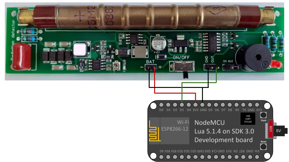
Fig. Connecting GGreg20_V3 to a classic NodeMCU board with ESP8266
Step 5. Select the GPIO pin on the controller that will register the pulses from GGreg20
If this is your first time dealing with ESP8266 and you do not know which GPIO is best to use for a pulse counter, we recommend using Сthe GPIO Planning and Application Standard for ESP8266-12 / NodeMCU / Lua projects, developed by alterstrategy.lab .
For example, it could be GPIO0 (D3). This pin is convenient because it has a built-in Flash button in most devices and boards based on the ESP8266 module – in case you need to check how the controller counts pulses without a sensor, it is possible to simulate pulses with a button. That is why all the examples in this publication are for GPIO0 (D3).
Step 6.. Connect the GGreg20_V3 radiation detector to the ESP8266 controller via the Out connector to the selected GPIO of the controller
As you can see, the connection is quite simple – you only need to supply power from the NodeMCU for the GGreg20 module, and connect the output (Out) of the sensor to the input (D3) of the controller and supply 5V to the micro USB connector of the NodeMCU.
Note. Note that you may not have GGreg20 at all – in this case, you can simulate the pulses by simply pressing the Flash button (GPIO0 / D3) a certain number of times per minute.
Flashing the ESP device with GGreg
Step 7. Build and write firmware for the controller
Before building the firmware, you need to validate the yaml file we created. This will protect us from file errors that we may have accidentally made.
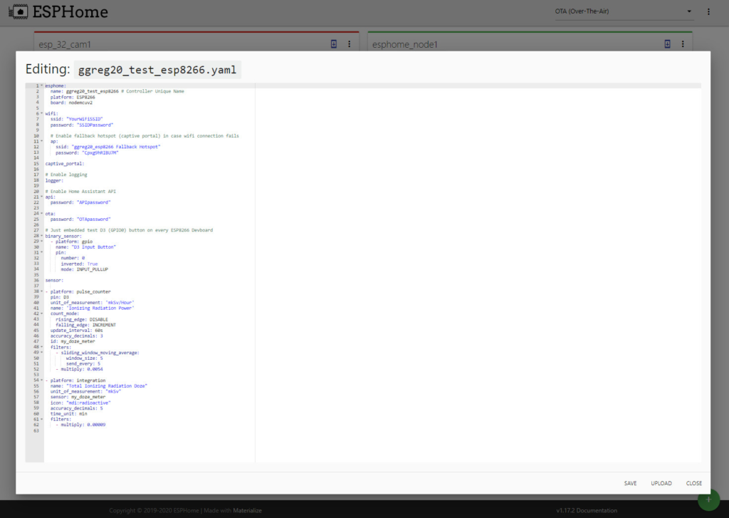
Fig. YAML code of the counter, which is planned to be flashed to the controller ESP8266
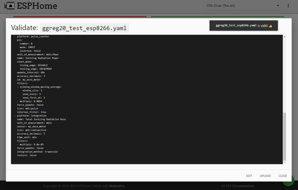
Fig. Yaml code validation was successful
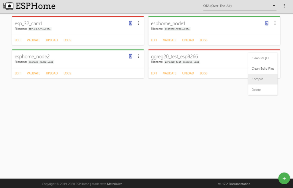
Fig. Start compiling the firmware binary for a specific yaml code
If the controller is new – you need to compile and download to the PC a binary firmware bin-file in the ESP Home interface – click DOWNLOAD BINARY after successful compilation.
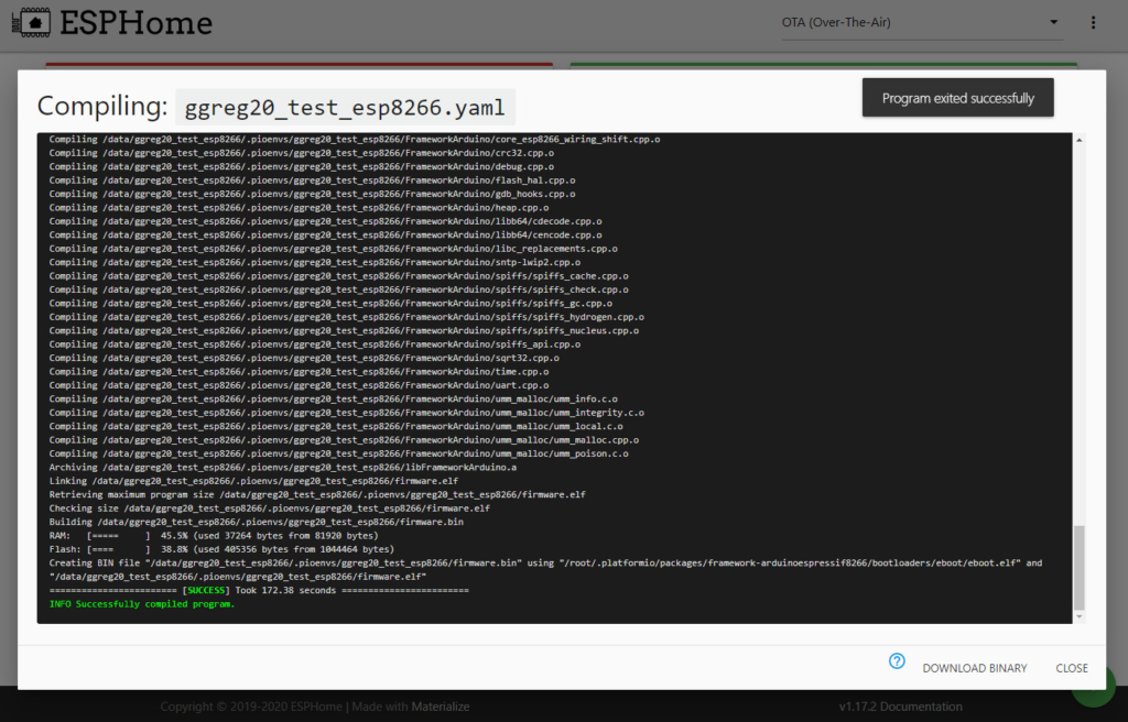
Fig. Compilation completed successfully
Next you need to write the firmware to the controller (ESP8266 / ESP32). This can be done by means of the ESPHome-Flasher utility. It can be freely found and downloaded via the Internet.
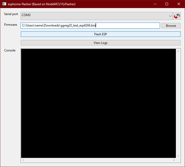
Fig. General view of the esphome-flasher utility
If the controller has already been flashed with ESP Home – just fill in the updated firmware over the air via OTA Update. But note that we deliberately do not consider this option to update the firmware, because the purpose of the article is to show how to connect the new GGreg20 with the new ESP8266 to Home Assistant.
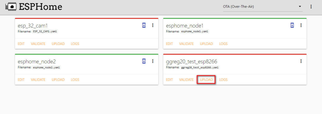
Fig. Launch of an alternative procedure for updating the firmware via WiFi-air – OTA Update
After flashing the firmware and restarting the new device, it is recommended to restart the Home Assistant server too.
Important! After starting the server you need to go to the menu Configuration -> Integration. Find there a new device that we flashed and connect it to the server configuration, if it is not connected automatically.
Conclusions
We’ve completed the following steps to connect GGreg20 to Home Assistant:
Step 5. Select the GPIO pin on the controller that will register the pulses from GGreg20
Step 6. Connect the GGreg20_V3 radiation detector to the ESP8266 controller via the Out connector to the selected GPIO of the controller
Step 7. Build and write firmware for the controller
Next, we look at the following steps in detail – part 3 :
Step 8. Check the log of the new ESP8266 controller with GGreg20 connected
Step 9. Check for new entities on the server side
Step 10. Add GGreg20 radiation sensor widgets to the Dashboard
Step 11. Add a push notification automation script to the Home Assistant application for crossing thresholds
That’s all. Good luck!