IoT-devices constantly promote the use of I2C bus as one of the best serial digital interfaces.
The I2C bus offers all the necessary functions:
- a simple physical interface: the SDA data and SCL synchronization signals require only two wires to connect to the bus;
- the addressing of devices on the bus with unique 7-bit addresses;
- identification of devices on the bus by their address or by unique identifiers (if provided by the chip manufacturer);
- hot device plugging / unplugging like Plug & Play;
- the unit is powered by the bus or by each module’s own power supply;
- the support for different supply voltages of devices on the bus (provided that the signals are matched to the voltage level);
- an advanced infrastructure of amplifiers, repeaters, splitters and multiplexers to build complex topologies offered by chip manufacturers;
All that allows about a hundred devices to be connected to the controller on a single interface at the same time. The I/O port budget of the main controller is minimal when the I2C bus is used to connect the sensors.
Sensors or actuators might be on an extension cord, or all the chips might be concentrated on one module. Or all chips can be focused on one module.
The master controller and slave devices can be powered independently. Or all devices on the bus can be powered from a common source.
The I2C is supported by the vast majority of microelectronics manufacturers. All popular controllers, IoT / Smart Home platforms, and related development environments are compatible with the bus.
Most IoT devices support the I2C interface as basic. Moreover, the support of the I2C bus is usually a decisive factor in the selection of chips in our projects. But any system has not only advantages. There are also shortcomings and hidden problems that we reveal in the publications.
Today we would like to talk about the software problem of choosing the right hardware sensors with I2C bus support. We will not go into the theory, but rather suggest a practical example using our devices.
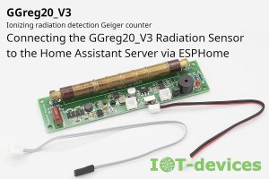
Let’s start with the popular radiation sensor module GGreg20 .
Example №1. GGreg20 and I2C GGreg20 and I2C
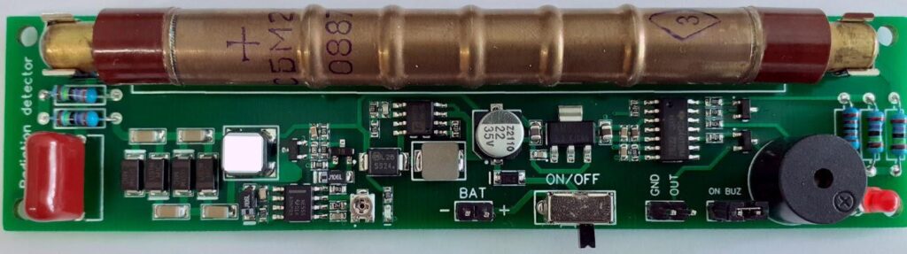
From time to time we are asked if it would be better to equip the GGreg20 module with the I2C interface and offer such a product as an alternative to the product with a pulse output, which is now GGreg20_V3.
In short, no. Let’s try to justify our opinion in more detail. Let’s try to justify our opinion in more detail.
We really like the I2C bus. We, moreover, already have an I2C interface splitter module, I2CHUB, which would be well suited to a hypothetical GGreg20 with I2C interface. So we can take a budget microcontroller – a companion like STM32, which must perform the necessary pulse calculations and give calculated values of the power and dose of ionizing radiation to the main controller at a low level via I2C interface.
But let’s ask ourselves how many common and very popular IoT platforms and microcontrollers will have driver support for such an I2C sensor? The answer will be disappointing since it is not an industrial sensor with a huge sales market.
The answer will be disappointing since it is not an industrial sensor with a huge sales market.
Certainly, our company needs everyone to be able to connect our sensors. It is our customers who must choose the type of controller or platform. We need to provide versatility for Arduino, ESP32 / ESP8266, Raspberry Pi, or for NodeMCU, Node-RED and ESPHome in Home Assistant, and many other IoT development environments that we might not have even heard of.
GGreg20 is now supported by any controller, development environment, and IoT platform, precisely because it has a versatile pulse output. If we equipped the GGreg20 with an I2C interface, we would have a completely different result.
Note . What if you make two interfaces on the GGreg20 module at once – pulse output and I2C? It would be very convenient, but in this case we believe that these costs at the expense of customers would be unjustified. The companion controller occupies a certain area on the module board. The I2C bus takes up twice as many controller ports as the pulse output. All this significantly increases the unit cost of the product. While the Pulse interface takes up only one GPIO controller with an interrupt handler and is much easier to program. And if we talk about maximum simplification, the GGreg20 module can work without a controller at all. The user can measure radiation (in circumstances that require it) only with a clock to record the measurement time in minutes.
We will next consider another example of two similar devices. They both have an I2C interface, but different application perspectives.
Example №2. I2CUI3, I2CUI4 and I2C
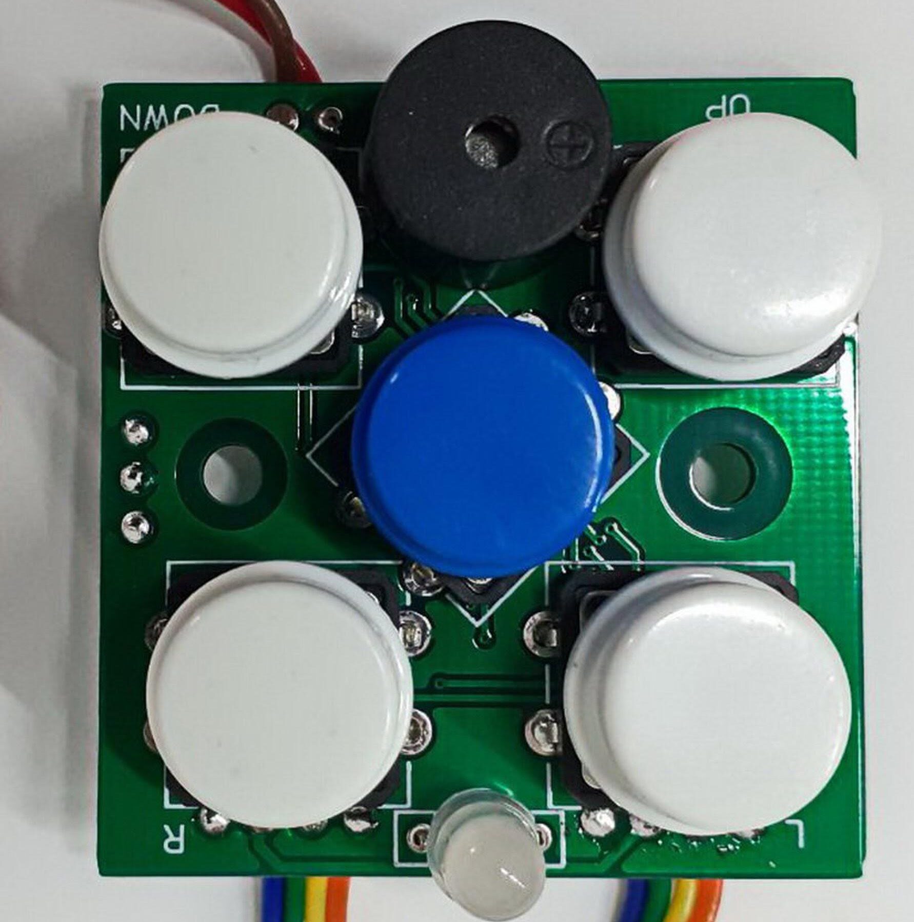
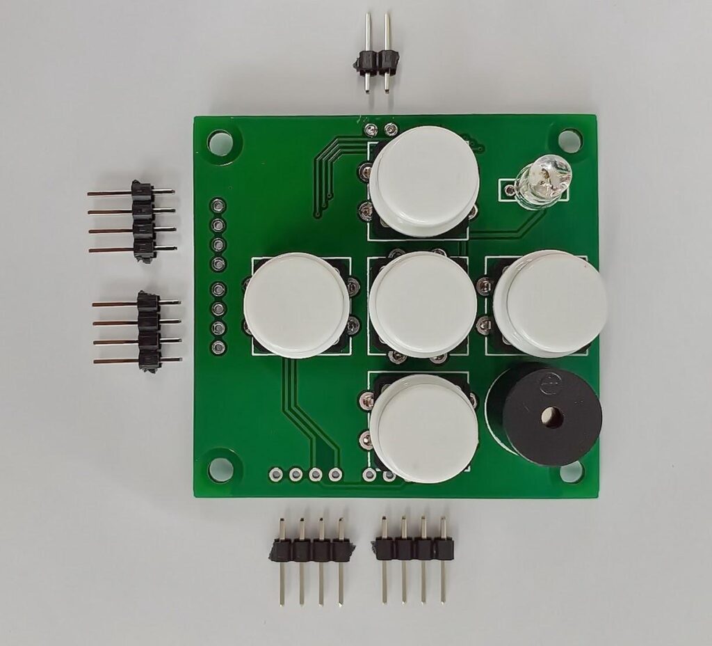
We first developed I2CUI3 – a useful and reliable product. It is a universal module of user interfaces with the I2C interface, which provides input of user instructions with the help of five navigation buttons and output of data to the RGB LED and the bazaar about the status or events of the IoT device. It is based on the 8-bit NXP PCA9538 port expander. For many years we have been using this chip for various tasks, including as the main component of the I2CUI3 module. The PCA9538 port expander is convenient, as it works semi-automatically after power supply and for some tasks does not require pre-programming at all, and therefore can work even without the main microcontroller.
And then it became clear that we need not 8-bit, but 16-bit similar module for certain tasks. So we created a new product with an I2C interface – I2CUI4 module based on the MCP23017 port expander chip.
For the new I2CUI4, we could use NXP’s older expander in the line. They have several 16-bit expander chips like PCA6416, PCA9539, PCA9575, PCA9673. But there are no official libraries for any of the chips either on the arduino.cc site or on the esphome.io site. There are also no drivers for the NodeMCU firmware.
There are only a few libraries for PCA9539 on Github, but neither Adafruit nor Seeed Studio has drivers for any NXP chip.
That is why the new product I2CUI4 is compatible with common platforms and has probably the most popular chip MCP23017 from Microchip Technology with I2C interface.
Thanks to that, our MCP23017-based product can boast a wide range of support by Arduino, NodeMCU, ESPHome / Home Assistant, Node-RED, Blynk, MicroPython, Raspberry Pi, STM32, and other brands. GitHub has hundreds of repositories with drivers in C / C ++, Python, JS, Lua, and other languages.
Conclusion
We gave two examples of identifying and solving the problem of driver support for devices equipped with an I2C interface from our own experience.
Unless you plan to provide on your own driver support for an I2C device you are about to buy, please pay attention to the hidden external risks described in this publication. You should choose a device, module, or chip with an I2C interface, which, in addition to other factors, will have the widest driver support among third-party systems. Special attention concerning compatibility and support should be given to the target microcontrollers, platforms, development environments. You have to be sure that all of these systems will support your chip before using it in your designs.
We have used these principles to develop two excellent products, GGreg20 and I2CUI4, to minimize the risks and avoid the problems mentioned above.
We hope you find this material useful.
Thank you for your attention.