To the attention of owners of controllers with a voltage level of 5V on GPIO (such as Arduino) to which GGreg20_V3 with 3V3 logic is connected.
The GGreg20_V3 output supports direct connection to the Arduino and we recommend powering both modules of the same power supply and turning them on at the same time.
However, if you plan to control the on / off of the GGreg20_V3 sensor regardless of the main controller being switched on, the following information may be useful to you.
For example, there may be a situation where the GGreg20_V3 detector has a separate power supply and the GGreg20_V3 is not switched on at the same time as the controller, but by a separate command from the controller or a physical switch manually.
In this case, processes occur between the devices, which with a difference of 3V3 at the output and 5V at the input can lead to the establishment of an indeterminate state on the controller port. Which in turn stops interrupt processing and, as a consequence, stops measuring the number of pulses coming from the sensor.
In this case, it is necessary to match the logic voltage levels between these two components.
We recommend doing this by following these steps:
1. It is necessary (as usual) to use the INPUT_PULLUP GPIO port mode.
For Arduino, the corresponding code is as follows:
pinMode(pin, INPUT_PULLUP);
where pin is the number of the I/O port; INPUT_PULLUP is a constant.
The interrupt handler has the usual settings for processing the input signal and looks like this:
attachInterrupt(digitalPinToInterrupt(pin), ISR(), LOW);
where pin is the number of the I/O port; ISR() is the identifier of the interrupt handler function; LOW is a constant.
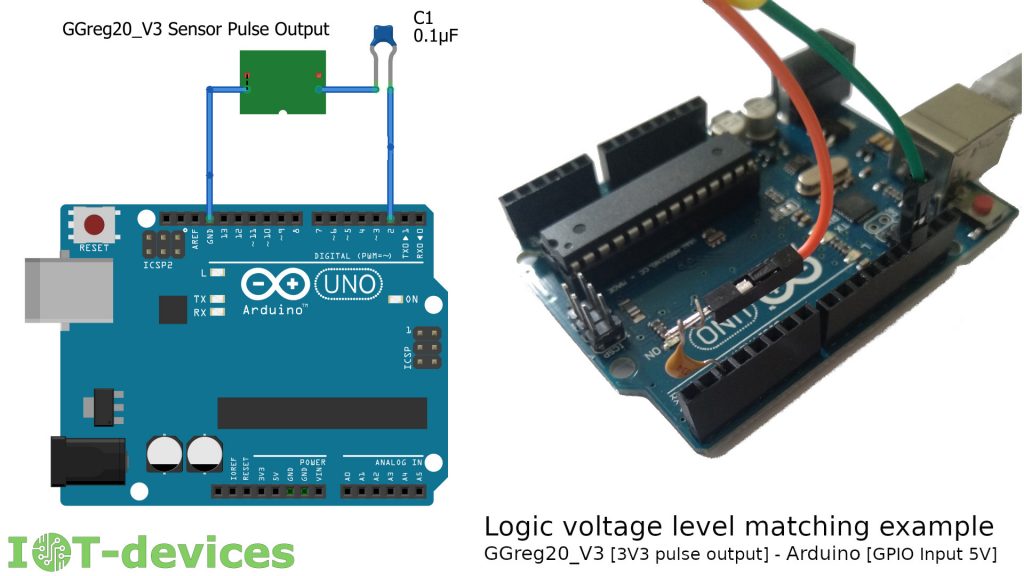
2. It is necessary to connect a 0.1uF ceramic capacitor in series in the signal circuit (wire between the pulse output of the sensor and the input GPIO of the controller). The figure shows a diagram and a photo of how the capacitor is connected. The presence of a capacitor makes it impossible to block the input of the controller and the circuit will work stably.
Note that this solution takes into account the complex internal processes that occur between the connected electronic components, which can not be described in a limited amount of this document and was chosen by experts as optimal to solve this particular problem.