The idea of this article arose as a result of development of the battery power supply unit of the X-ray meter ( GGreg20 detector plus controller ESP12.OLED_V1 ).
Developers demanding quality solutions in the development of electronic devices will agree with the statement that a quality power supply module for IoT devices can cost more than the rest of the device.
Our principle – not to copy other people’s decisions, threw us work in the process of developing a universal and optimal power supply module. Moreover, we had to violate this principle, because the datasheet of manufacturers deserves the highest trust. The desire to make the device as simple and miniature as possible suggested: “put a Li-Ion battery and a linear stabilizer to convert the battery voltage to 3V3 and that’s it!” It did not work because the battery voltage is too low to effectively stabilize during battery discharge time.
On the other hand, there is a fairly large pool of devices that need to have 5 volts to power.
Around this problem with the inconvenient voltage level of lithium batteries and accumulators developed a whole segment of chips – DC / DC converters, whose task is to increase or decrease the voltage from 2.8 to 4.1 Volts so as to obtain a stabilized voltage of standard levels.
We have selected and successfully tested the MT3608 chip. It does not make sense in this publication to give a diagram of the converter. The reader will find it in the dataheet ( prom-electric.ru/media/MT3608.pdf ). This document provides a diagram of a converter with an output voltage of 5 volts. It is convenient that the chip has a feedback pin for the output voltage stabilization loop. The whole circuit of the converter consists of a chip, two resistors, a choke and a capacitor.
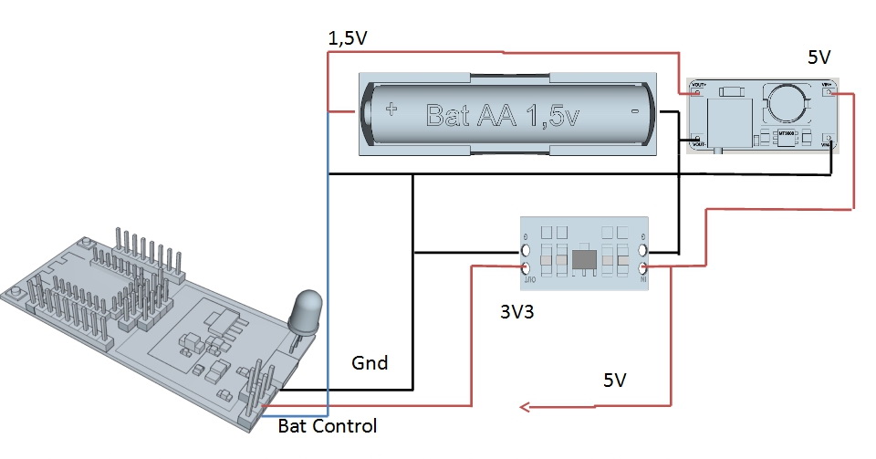
To simplify the creation of a prototype power supply purchased two more modules, which combined, as shown in Fig. 1, resulting in a layout of the power supply with the following characteristics:
- Control of charging of Li-Ion batteries on the popular TP4056 chip, charge current up to 1 A;
- Thanks to the use of the module to increase the voltage from 2 to 5 volts, we convert it into a stable output voltage of 5 volts. Load current 1 A;
- We use only one AA element. Warning! According to the characteristics of MT3608, the minimum level of input voltage = 2 V, but the test showed a good result at a voltage of 1.5 V. We do not recommend repeating this scheme (see conclusions and recommendations);
- At the output of the voltage stabilizer module we get 3.3 volts, load current (without radiator) 500 mA.
Power supply testing for IoT devices.
Option A: Power supply from one galvanic cell. For testing, the cheapest AA salt battery (1.5 volts) was installed without a charging module.
A DCDC Booster is connected to the battery output, which converts 1.5 volts to 5 volts. To the output of 5 volts connect a 3.3 volt stabilizer. The tests were performed under the power supply of the controller ESP12.OLED_V1 , which consumes 60 mA. The power supply is connected to the controller via a 5 volt input. To control the discharge process, the batteries plus batteries were connected to the ADC (ADC) of the controller, and the measurement results were recorded in Log.
- Duration of continuous work 5 hours 20 minutes;
- The initial voltage on the battery is 1.53 volts;
- Final battery voltage 0.92 Volts;
- The output voltage of 5 volts is kept at the level of 5 ± 0.1 volts at all times.
Option B. As an electrochemical source, install a Li-Ion AA battery with a capacity of 800 mA / h (3.7 volts).
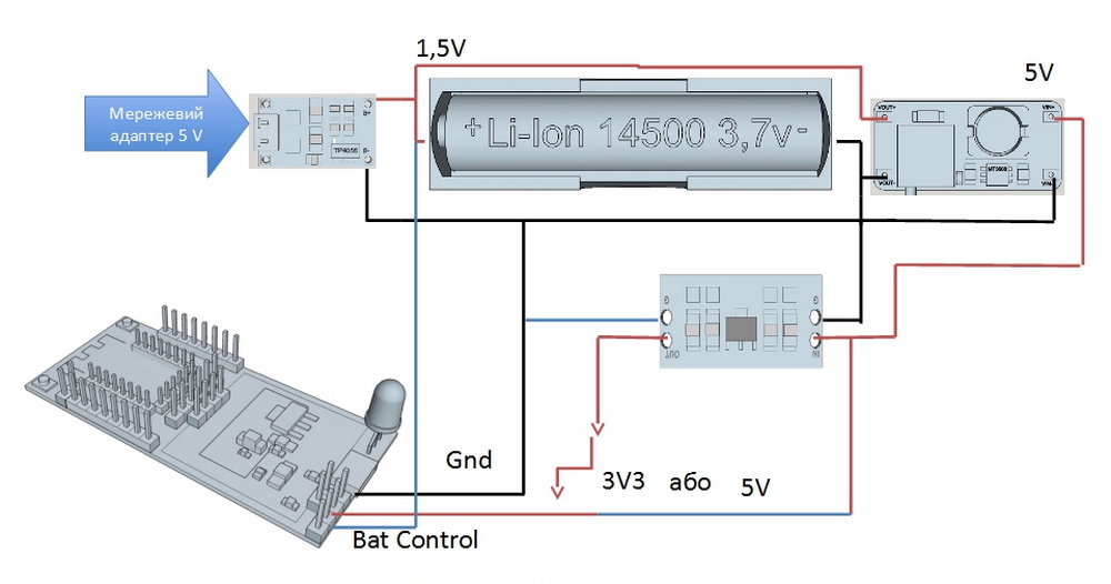
Tests are performed in the same conditions except: for completeness of testing the power supply is connected to the controller ESP12.OLED_V1 through input 3V3.
- Duration of continuous work 10 hours 30 minutes.
- The initial battery voltage is 4.1 volts.
- The final voltage is 2.8 volts.
- The output voltage of 5 volts is kept at the level of 5 ± 0.1 volts at all times.
- The output voltage of 3.3 volts during the entire discharge time of the battery was kept at the level of 3.28 – 3.29 volts.
Satisfied with the test results, we felt very smart, but also “smart cry” .
After testing, they had plans to produce their own power supply module for IoT devices, even drew a 3D model:
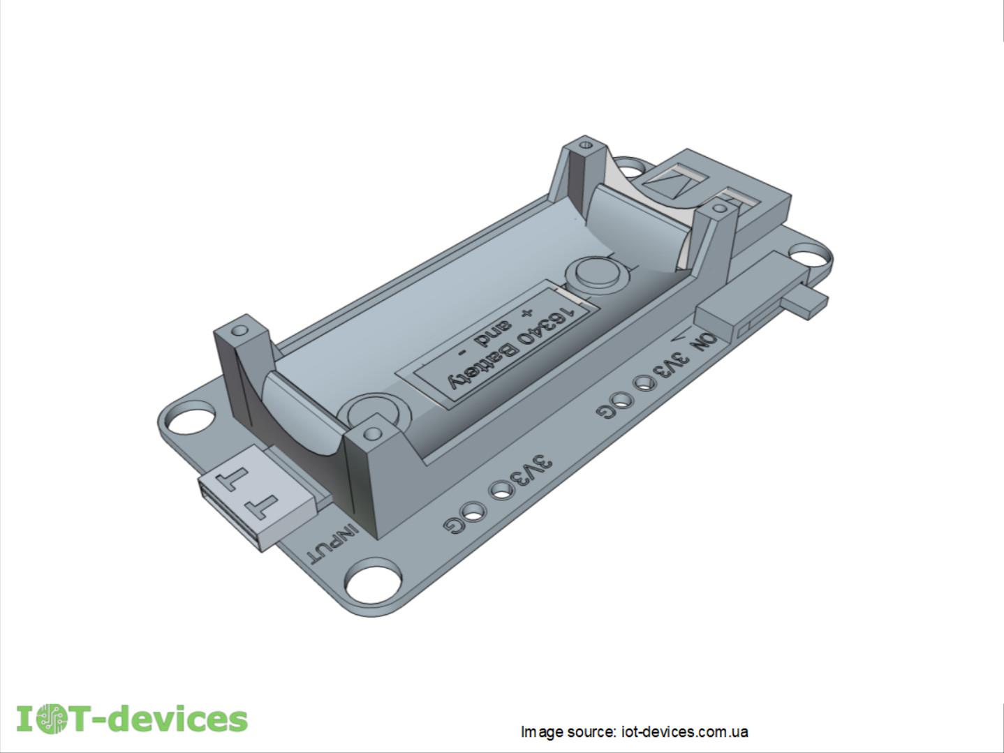
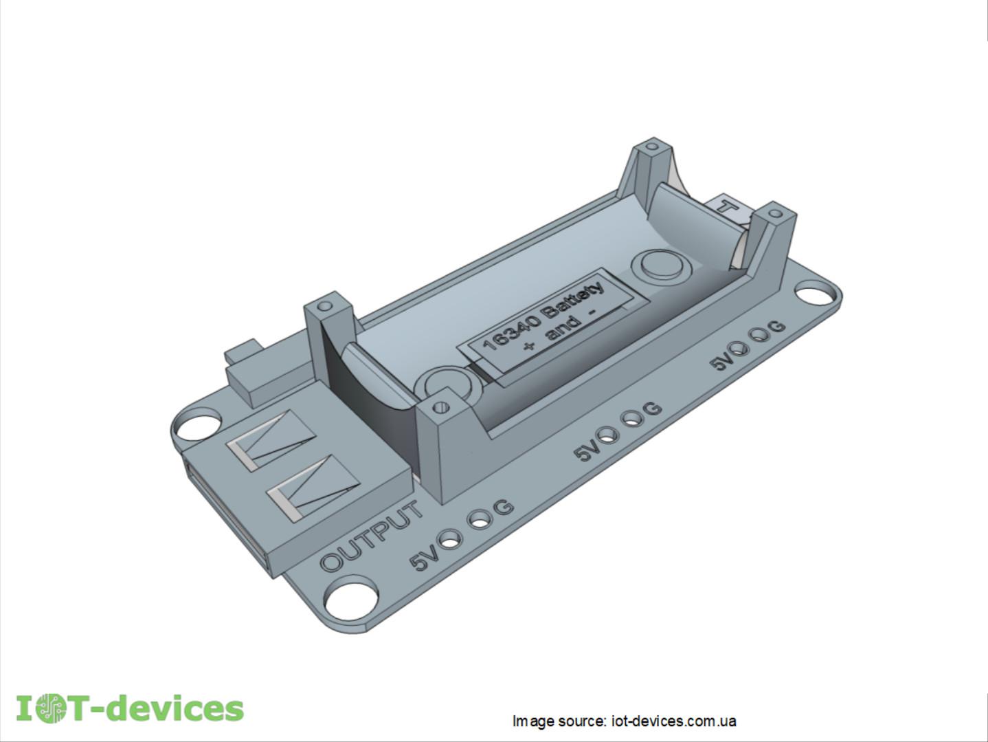

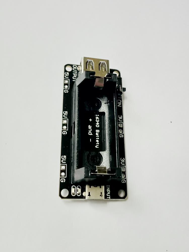
But, just in case, did a search for analogues. Found a wonderful and fairly inexpensive analogue.
You can order these modules from us:

Conclusions and recommendations:
- Boost converters significantly improve the technical characteristics of power supplies of compact devices. In the battery version with two galvanic cells or lithium cells CR2032, CR2477 (3 Volts), we got even better results. But the choice of battery must be made carefully, taking into account the requirements of the project.
- Before you spend time developing a device, carefully check if it makes sense. It is difficult to compete with modern China.
- We will be glad if our article will help you to make from the bought modules really universal, cheap and convenient power supply unit of controllers. If you want to buy ready-made, it will also be a good choice.