Exemption from liability
The company IoT-devices, LLC does not bear any responsibility for possible direct or indirect damage or costs that may be incurred by anyone in the process of using the electronic modules or following these instructions. These are just tips that take into account experience and best practices for dealing with electronic systems.
Users and readers should use common sense, and most importantly, follow the rules for handling electrical installations and comply with local laws that may establish requirements for the procedure of qualified performance of work on connecting electronic components to each other.
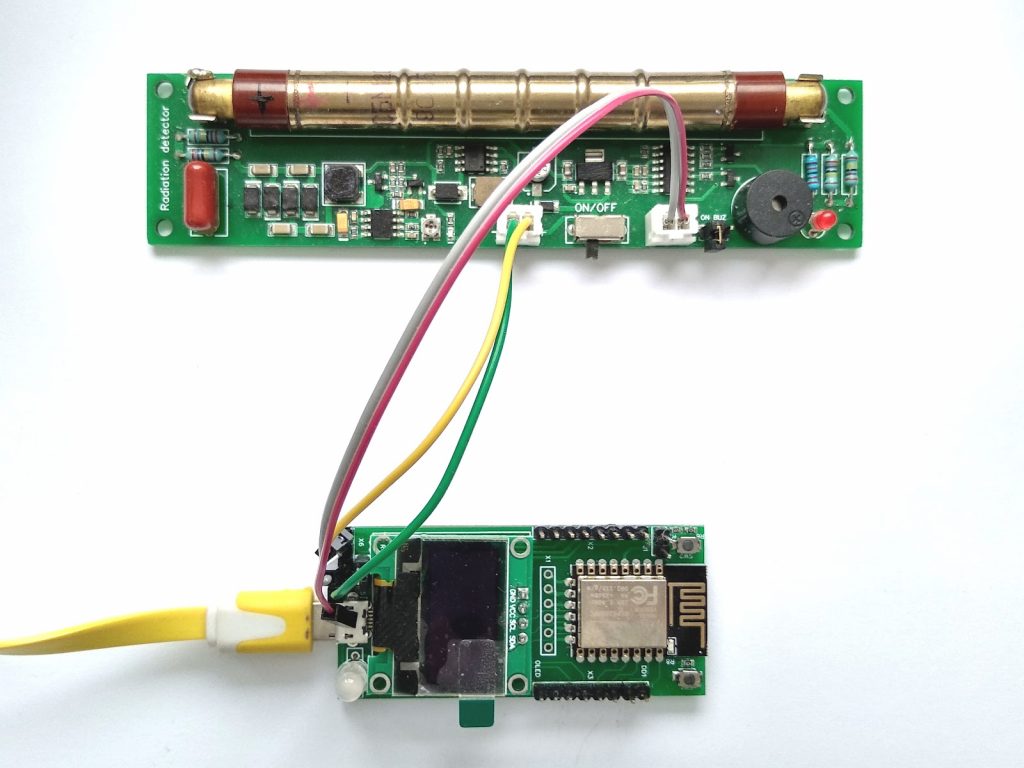
This document is for the attention of those users who are going to connect two GGreg20_V3 and ESP12.OLED modules together.
This document contains a connection diagram, which in particular shows
- all the necessary interface signals and ports that need to be connected, including the module power supply scheme.
- Also, the diagram contains data on the connection of the USB-UART converter for the possibility of programming and/or flashing the ESP8266-12F module embedded on the ESP12.OLED board.
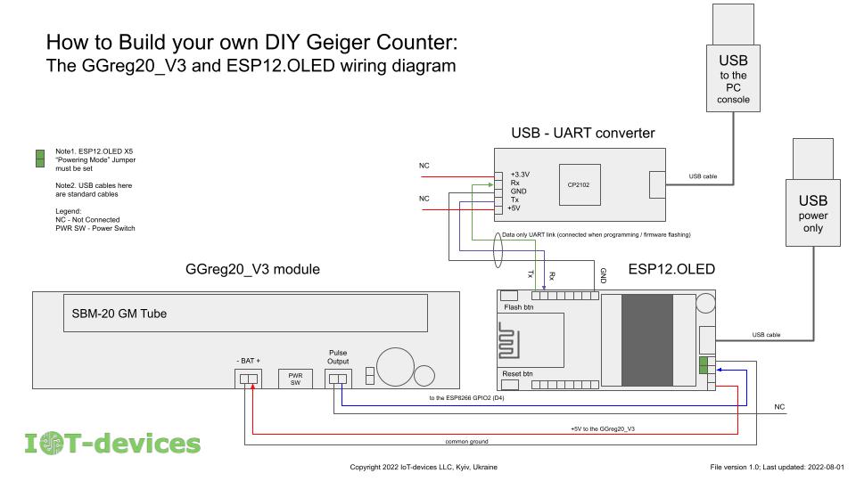
Note that some interface signals are marked NC on the schematic, meaning they are not connected.
This is especially important when it comes to connecting the USB-UART adapter: according to the scheme, it is forbidden to connect the power supply circuits of the adapter (+5V and +3.3V) to the ESP12.OLED module!
IMPORTANT ! Incorrect connection or violation of the connection scheme can lead to counter current. Doing so may damage the equipment.
GGreg20_V3 product pages:
https://www.tindie.com/products/iotdev/ggreg20_v3-ionizing-radiation-detector/
ESP12.OLED product pages:
https://www.tindie.com/products/iotdev/esp12oled-universal-esp8266096oled-mcu-board/