How to create a layout (without using a soldering iron) to measure the physical parameters of the environment.
An article for programmers who do not like to design or for electronics who want to get a ready-made complex for mastering programming.
This article will be useful for beginners who are not yet familiar with MCU architecture.
The first steps.
We know from our own experience that when you first pick up a miniature module and see a lot of “little things” on it and you do not know the terminology, do not understand the difference between input and output, look for the usual keyboard and display, there is a feeling that you have no chance master this module. But if you overdo it and connect it to the power supply, it is difficult to understand whether it works.
So what is it – a controller?
I’m sure most readers know this, but if they don’t, they’ll forgive me for that explanation. When children ask me such questions, I warn that it will not work out. Life may not be enough to understand deeply. But nowadays, everyone thinks they know what the word “computer” means, so let’s try to easily compare a computer (PC) and a controller.
The classic PC is focused on the role of a personal intelligent assistant and therefore these systems are manufactured and sold as a wider or simpler group of devices that are convenient for a person to communicate with a “smart” when performing any information processing work. I called the processor (CPU, central processing unit) installed on the well-known “motherboard” “smart”.
The controllers also have a CPU, but the developer of each controller surrounds the CPU with such electronic components and devices that it performs some specific work. The board ESP12.OLED_V1 has a MCU (Micro controller unit) ESP8266-12F and the MCU has a built-in CPU.
For example, a digital thermometer controller has:
- MCU,
- power supply components;
- temperature sensor;
- buttons, switches, etc .;
- and some means for displaying information.
The MCU has components for programming. When the programmer has already written the program in the memory of the MCU (“stitched”), and the electronics have connected electronic components, the controller begins to “live” according to the script created by the developer. It waits for control commands, receives and converts information to visualize it as designed by the developer and programmed by the programmer.
Thus, the washing machine controller is connected to valves, motors, sensors, buttons, displays and is programmed to perform laundry.
Developer fees
There is a special category of controllers – developer board , which consist of MCUs and components that are needed to simplify power supply, simplify the connection of the console (PC with special software), as a tool for entering and editing programs, managing installed ports, to which it is convenient to connect sensors and actuators. It’s hard for me to imagine an amateur who will be able to use a “naked” MCU on their own without special equipment and tools.
This publication will talk about the controller ( developer fee ) ESP12.OLED_V1 , to which we will connect external and internal sensors to measure atmospheric pressure, temperature, humidity, dew point, altitude relative to sea level indoors and outdoors.
Layout components
Required components and equipment to create a layout:
- Controller ESP12.OLED_V1 set 1 .
- HTU21 module or similar digital (I2C) sensor. You can buy it in online stores.
- BME280 3V3 module. You can buy it in online stores.
- Power supply (5-volt AC adapter) or 4.5 to 6-volt battery or accumulator.
- Connecting wires
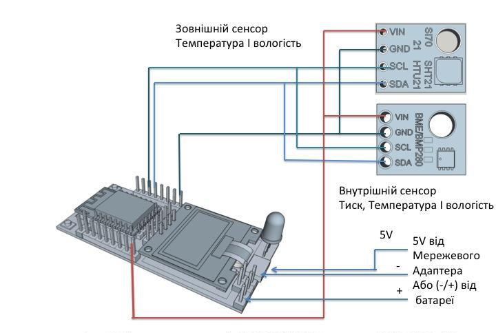
Figure 1 shows a diagram of the connections. Additionally, use the documentation for the controller and modules to prevent errors and damage to the modules.
Carefully study the options of ESP12.OLED_V1 kits to make the best choice of controller board for your project. In this publication, we recommend that you select ESP12.OLED_V1 Board 1 as the controller. This is the maximum set. If your project, for example, provides information not on the display, but on the browser, select set 2 (without display). In this case, the sensors can be connected to the I2C connector in place of the not installed display, and the device will be cheaper.
Practical advice.
We don’t know how you designed your project, but we guess that, for example, you will need a keyboard to configure the device. The board already has a “Flash” button, the purpose of which is one of the firmware tools. But at the stage of program execution, it can be used as a normal function button. If you read our other publications, you will find a lot of information useful for designing and programming devices.
Order a Controller ESP12.OLED_V1 set 1
We wish you success and satisfaction with the results of creativity.