In Episode 3, we talked about GGreg20 recorder of radioactive particles with access to the controller
What do you need a controller for?
Admittedly, developers of electronic equipment (and we are no exception) are trying to find a solution without the use of a controller, because they are afraid of programming.
In order not to “connect” with programming, we tried to find a ready-made module on the Internet with a screen and a pulse counter.
Dear gentlemen! We do not recommend wasting time. Even if you find a module that counts pulses and displays their number, it will not be X-rays or Sieverts, but simply the number of pulses or frequency. And the price of such a module is like the whole dosimeter.
So what do you need a controller for?
- count the number of pulses over a period of time;
- calculate a number of parameters related to the level of radiation and human protection: the current level, the accumulated level; detection and signaling of exceeding the set thresholds, recording the time and place of measurements, construction of diagrams and much more that can be useful or vital. In addition, each type of Geiger-Mueller tube has its own original characteristics, which are calculated;
- display the results of measurements and calculations on the display;
- remember measurement statistics;
- use the means of radio communication with a computer (Wi-Fi);
- measure and display the battery charge level.
On the controller, each developer can develop their own script for programming and data visualization. On the other hand, the controller is the same miniature, simple and cheap ready-made module that we tried to find. If you think you weren’t born a programmer, that’s not true. The controller gives you the opportunity to start with the simplest, and after a while to write the coolest program in the world. Moreover, over time you have the opportunity to rewrite and update programs to make them even better.
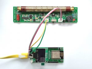
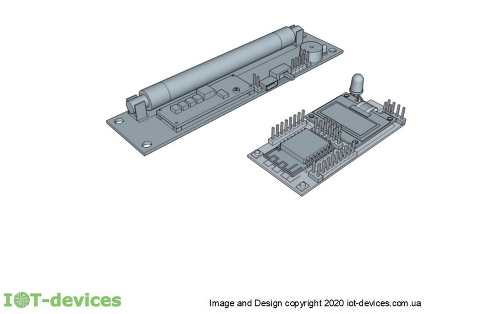
D GGreg20 detector can be connected to any controller. It can be NodeMCU or Arduino, which can be purchased in online stores. If you use a NodeMCU, you will have to somehow connect and secure the display. Using the Arduino, there will be two problems: lack of display and Wi-Fi. Using our GGreg20 + kit ESP12.OLED , connect the two boards as shown in Fig. 2, turn on the power and program. Everything is provided on our boards.
We suggest using our ESP12.Oled controller module to create a full-fledged convenient dosimeter, and more.

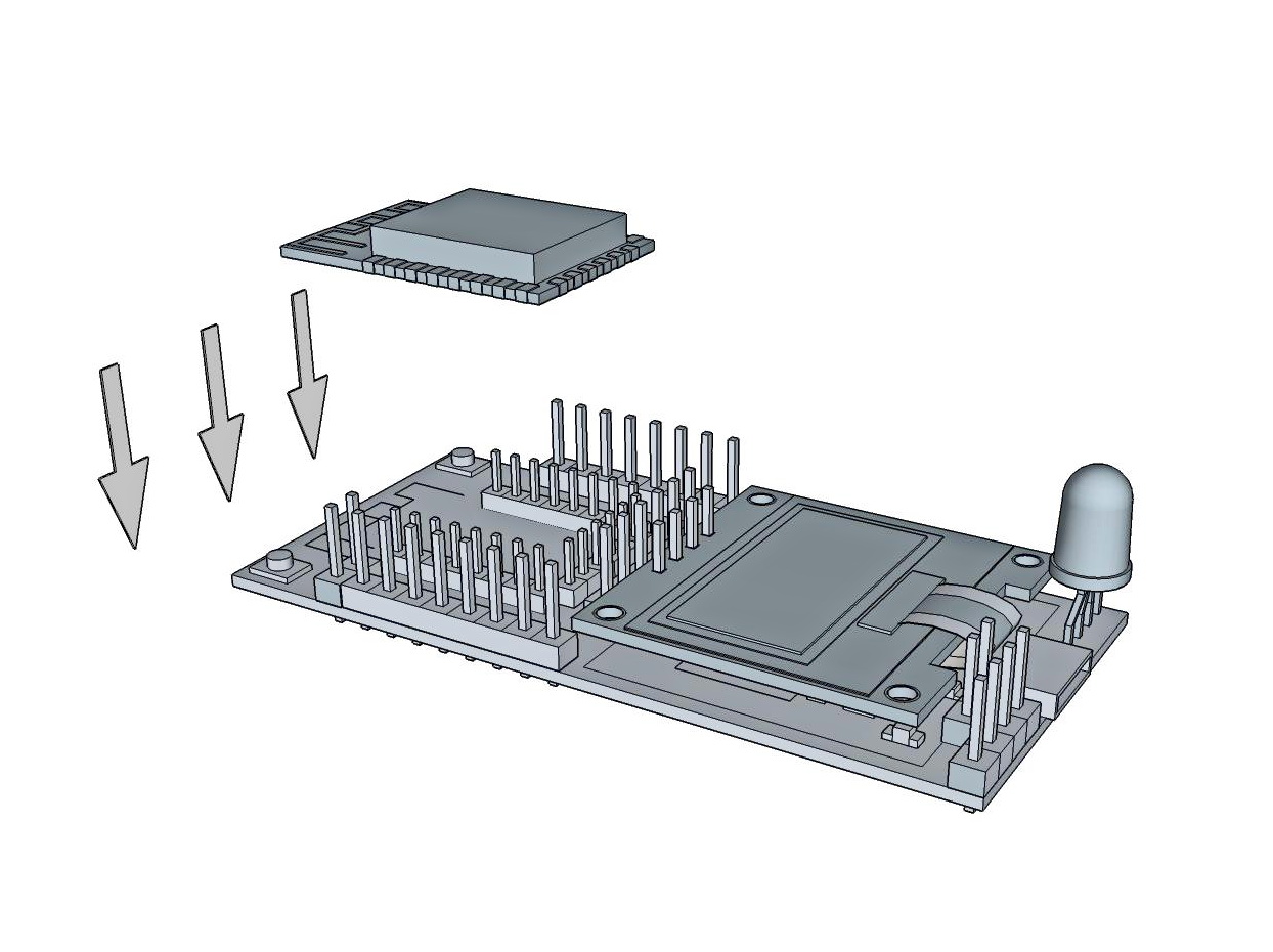
ESP12.Oled controller , developed on the basis of the ESP8266-12E (F) module manufactured by Espressif and a graphic display, which in the form of a module is also placed on the controller board. What makes our controller special? We have developed a kind of transformer. You can use the controller as:
- Programmer MCU 8266-12E (F), on which without soldering you can install the MCU for programming and then remove and transfer to the user controller.
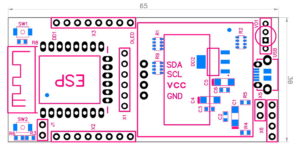
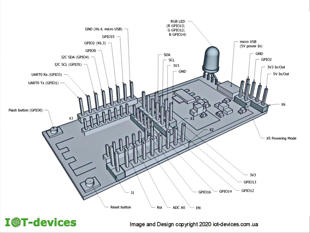
- Boards for designing your own custom controller at home using available tools. In Fig. 4. and in Table 1. we have displayed the maximum amount of information required to create your own controller based on the ESP12.OLED board in the minimum configuration.
- Custom controller with permanently soldered MCU, which can be programmed and used in devices without a display and for visualization to limit the capabilities of the RGB LED;
- After all, it can be a complete controller with a display, LED, stabilizer, serial interfaces, GPIO, power connector from the microUSB charger or an alternative interface for battery power and much more.
The power mode configurator provides modes master or glory . This means that the controller can act as a master with the provided switches and connectors and it is possible to power the subordinate modules with a voltage of 3.3 Volts or 5 Volts (if in Arduino projects). The controller can also act as a voltage supply of 3.3 volts or 5 volts relative to other modules.
- To program the controller, connect ESP12.OLED through the UART connector to your computer, using the UART-USB interface converter on the CP2102 chip or similar, which is widely and cheaply offered by the electronics market: CP2102 module .
- Important note : If you went by creating your own controller based on the minimum set ESP12.OLED, have already decided on additional components and made the firmware necessary for your project modules – solder the PINs of all components you install to the board. So it will be more reliable.
- Table 1.
| Mark on the board ESP12.OLED. | PIN # | Name in ESP8266-12 | Appointment in ESP12.OLED | IN / OUT | Physical “lift” on the board ESP12.OLED | Active level |
| X2 | 1 | RST | RST button (Sw2) | In | Pull-up | Low. On this pin it is possible to connect in parallel one more Reset button for removal on the case panel. |
| 2 | ADC | ADC input – measurement of power supply voltage | Analog In | Divider | A divider is installed to measure the battery voltage level or from USB | |
| 3 | EN | – | Pull-up | |||
| 4 | GPIO16 | Deep-Sleep-Wake-up | Out | Pull-up | Low | |
| 5 | GPIO14 | VD1 Led Blue | Out | Pull-up | Low | |
| 6 | GPIO12 | VD1 Led Green | Out | Pull-up | Low | |
| 7 | GPIO13 | VD1 Led Red | Out | Pull-up | Low | |
| 8 | VCC | Power supply 3V3 | – | |||
| X1 | 1 | GPIO11 | As needed | |||
| 2 | GPIO7 | As needed | ||||
| 3 | GPIO9 | As needed | ||||
| 4 | GPIO10 | As needed | ||||
| 5 | GPIO8 | As needed | ||||
| 6 | GPIO6 | As needed | ||||
| X3 | 1 | GND | GND | Port for connecting the USB converter Common GND bus | ||
| 2 | GPIO15 | HSPI CS | Out | Pull-Down | Low | |
| 3 | GPIO2 | Pulse input | in | Pull-up | Low | |
| 4 | GPIO0 | Flash button (Sw1) | In | Pull-up | Low. This pin can connect a parallel button | |
| 5 | GPIO4 | I2C SDA | In / out | Pull-up | Port for connecting components with I2C: SDA bus | |
| 6 | GPIO5 | I2C SCL | In / out | Pull-up | Port for connecting components with I2C bus: SCL | |
| 7 | RX | UART data input | In | – | Port for connecting the USB converter: RX | |
| 8 | TX | UART Data output | Out | – | Port for connecting the USB converter: TX | |
| X5 | 1 | – | Power mode | Switch | ||
| 2 | – | Power mode | Switch | |||
| X6 | 1 | – | Power input from battery or other component 4.5 – 6 Volts, or output 5 Volts to another component when powered by USB. | Warning! | If the X5 switch is installed, then the power supply from X6 (1) or USB .. If the power is 3V3, coming through X6 (2) or X2 (8), then remove the X5 switch. | |
| 2 | 3V3 | Input / Output 3V3 | In / out | |||
| 3 | Data (GPIO2) | Pulse data input | In | The source of the pulses is a Geiger meter or a meter of water, electricity, etc. | ||
| 4 | GND | GND | ||||
| J1 | 1 | GPIO16 | On / Off Wake-up after Deep-Sleep | – | – | – |
| OLED SDA | 1 | GPIO4 | I2C Data | In / Out | Pull-up | Low |
| OLED SCL | 2 | GPIO5 | I2C Clock | In / Out | Pull-up | Low |
| OLED VCC | 3 | VCC | 3V3 | In / Out | ||
| OLED GND | 4 | GND | GND | COM |
- Dimensions ESP12.OLED: 65x30x10 mm.
Detailed instructions on how to connect and use the controller modules can be found in the product descriptions: GGreg20 ,, ESP12.OLED