We offer you the procedure of connecting the GGreg20 Geiger counter (sensor) in combination with the main controller ESP8266 or ESP32 to the Home Assistant server via the ESP Home plug-in.
If you already have experience setting up and deploying devices in ESP Home running Home Assistant, you can skip the introductory sections and go straight to the example of a configuration yaml file that you can use as a basis for your own system and devices.
All sample files are working and run on a real-deployed server and controller ESP8266 with a GGreg20 Geiger counter. ESP32 is also supported by ESP Home and on the example of ESP8266, the reader can make a variant of the yaml file for the ESP32 platform. In this publication, we demonstrate how to work with ESP32 in a limited way, because in terms of ESP Home and Home Assistant settings, the ESP8266 and ESP32 platforms are almost the same.
Note . This publication is suitable for all versions of the ionizing radiation detector manufactured by IoT-devices: GGreg20_V1, GGreg20_V2, GGreg20_V3
Since the entire line of these detectors is focused on the SBM-20 tube, all versions of the devices have the same algorithm and coefficients for calculating the power level and dose of ionizing radiation.
The accuracy of the measurement is affected only by the individual properties of the SBM-20 tube installed in each GGreg20_V3 detector. The specifications of the tube manufacturer indicate a limit range of measurement accuracy of 20% . On practice, this means that two identical GGreg20 devices, but with different SBM-20 tubes, can give results (not more than) with the specified deviation in the number of pulses.
Steps to connect GGreg20 to Home Assistant
Next, we consider in detail the steps for connecting a detector (sensor) GGreg20. Honestly, we have to cite a lot of text and pictures to explain some important points – because of this, the publication seems procedural horror. It does not! All these steps are simple, automated and performed in 15-20 minutes.
Server
Step 1 . Install (or start) the Home Assistant server
If you already have a server installed, just start it. If you need to deploy the server, we recommend that you review the instructions we developed for deploying Home Assistant in a virtual machine running Windows 10
ESP Home plugin for Home Assistant
Step 2 . Connect the ESP Home extension for the Home Assistant server via the Supervisor -> Add-on Store menu
The procedure for installing an official plugin, such as ESP Home, in Home Assistant is quite simple. We recommend that you review Step 8. Installing the ESP Home Plugin (Option) the instructions mentioned earlier.
YAML-config of the new ESP device with GGreg
This is a key part of this publication, which interests us more than any other general data on the preparatory steps of the environment. In steps 3 and 4, we will develop our own config for ESP with GGreg based on real-world examples from our Home Assistant test server.
Step 3. Download the ready example of a batch yaml-configuration file of the GGreg20_V3 device for ESP8266 from our website
The YAML file is a common text script file in Home Assistant, in this case with instructions for ESP Home, which are used when building the firmware.
We have developed such a file for ESP8266 and GGreg20 and posted it on our website for free download and use by anyone who needs to connect GGreg20 to Home Assistant via ESP Home. You can download the file by following this link .
The full file you just downloaded has the following content:
Let’s consider the main parts of the ggreg20_esp8266_esphome.yaml file prepared by us.
To calculate the value of the ionizing radiation power of microsieverts per hour, use Pulse Counter Sensor – an API-component of the ESP Home plug-in:
https://esphome.io/components/sensor/pulse_counter.html
This part of the yaml code is responsible for that:
sensor:
- platform: pulse_counter
  pin: D3
  unit_of_measurement: 'mkSv/Hour'
  name: 'Ionizing Radiation Power'
  count_mode:
    rising_edge: DISABLE
    falling_edge: INCREMENT
  update_interval: 60s
  accuracy_decimals: 3
  id: my_doze_meter
  filters:
    - sliding_window_moving_average: # 5-minutes moving average (MA5) here
        window_size: 5
        send_every: 5
    - multiply: 0.0054 # SBM20 tube conversion factor of pulses into mkSv/Hour
To calculate the total radiation dose received in microsieverts, the Integration Sensor, also a component of the ESP Home API, is used:
https://esphome.io/components/sensor/integration.htm
This part of the yaml code is responsible for that:
- platform: integration
  name: "Total Ionizing Radiation Dose"
  unit_of_measurement: "mkSv"
  sensor: my_dose_meter # link entity id to the pulse_counter values above
  icon: "mdi:radioactive"
  accuracy_decimals: 5
  time_unit: min # integrate values every next minute
  filters:
    # obtained dose. Converting from mkSv/hour into mkSv/minute: [mkSv/h / 60] OR [mkSv/h * 0.0166666667].
    # if my_dose_meter in CPM, then [0.0054 / 60 minutes] = 0.00009; so CPM * 0.00009 = dose every next minute, mkSv.
    - multiply: 0.0166666667
Also, in order to be able to test the pulse counter without the GGreg20 sensor, a discrete Flash sensor ESP8266 has been added to the configuration – on the same GPIO0 (D3) as the Pulse Counter – but another ESP Home API component, GPIO Binary Sensor, is already used:
https://esphome.io/components/binary_sensor/gpio.html
This part of the yaml code is responsible for that:
binary_sensor:
  - platform: gpio
    name: "D3 Input Button"
    pin:
      number: 0
      inverted: True
      mode: INPUT_PULLUP
The ESP Home plugin has sufficient documentation for these components with examples, so we will not go into detailed explanations. Where we saw fit, we added comments inside the yaml code.
Step 4. Create (based on the example) in ESP Home the appropriate yaml configuration file
After downloading the file, we suggest you open it with any text editor and become familiar with its contents.
Next, in the interface of the ESP Home plugin on the Home Assistant web page with administrator access rights, you need to create your own yaml file by clicking “+” and answering a few initial questions of the wizard.
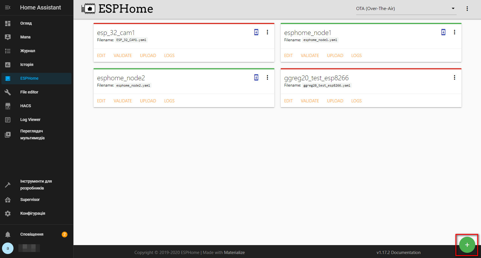
Fig. General view of the ESP Home plugin interface in Home Assistant
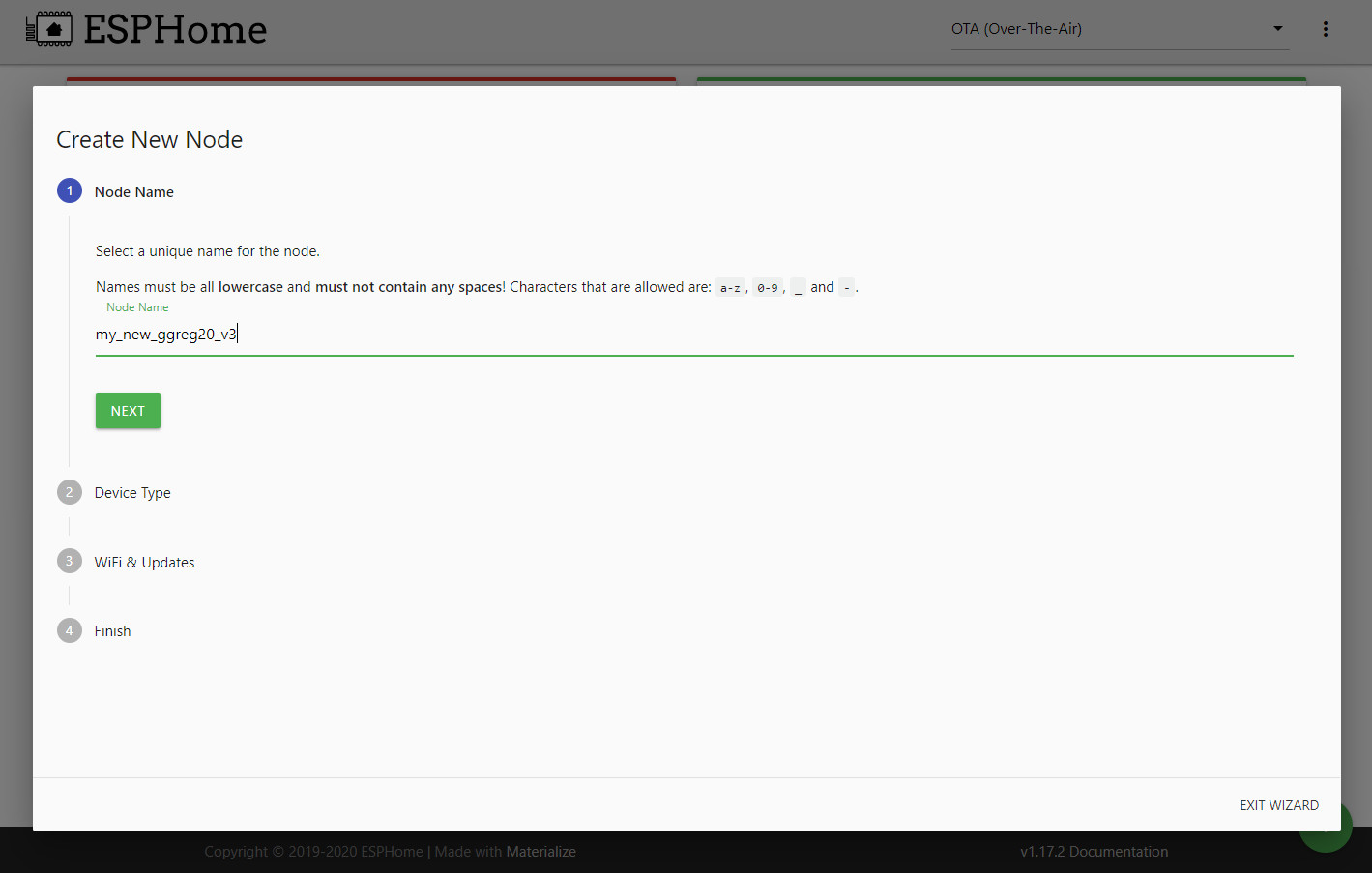
Fig. We give the name to our new device
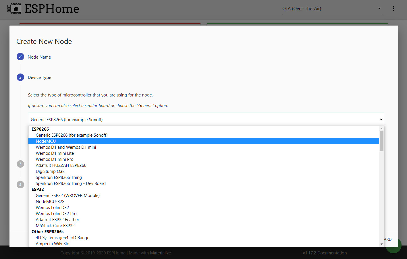
Fig. Choose the right platform according to the type of controller
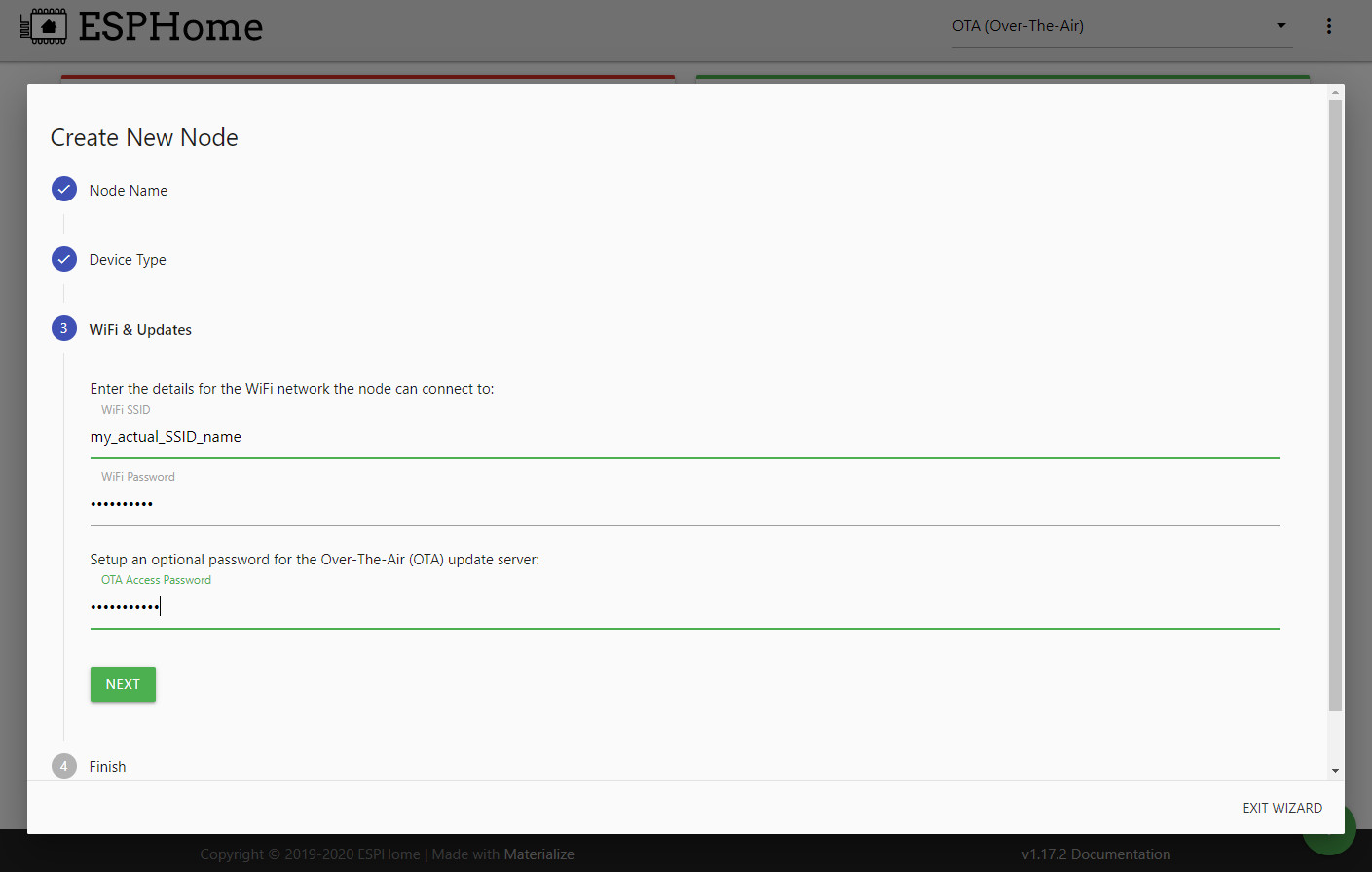
Fig. Specify the parameters of the WiFi router and password for OTA update
After completing the “wizard”, a file with the basic parameters that we have already configured appears in the ESP Home interface. Now you need to add to this file the parts that you will find in the ggreg20_esp8266_esphome.yaml file.
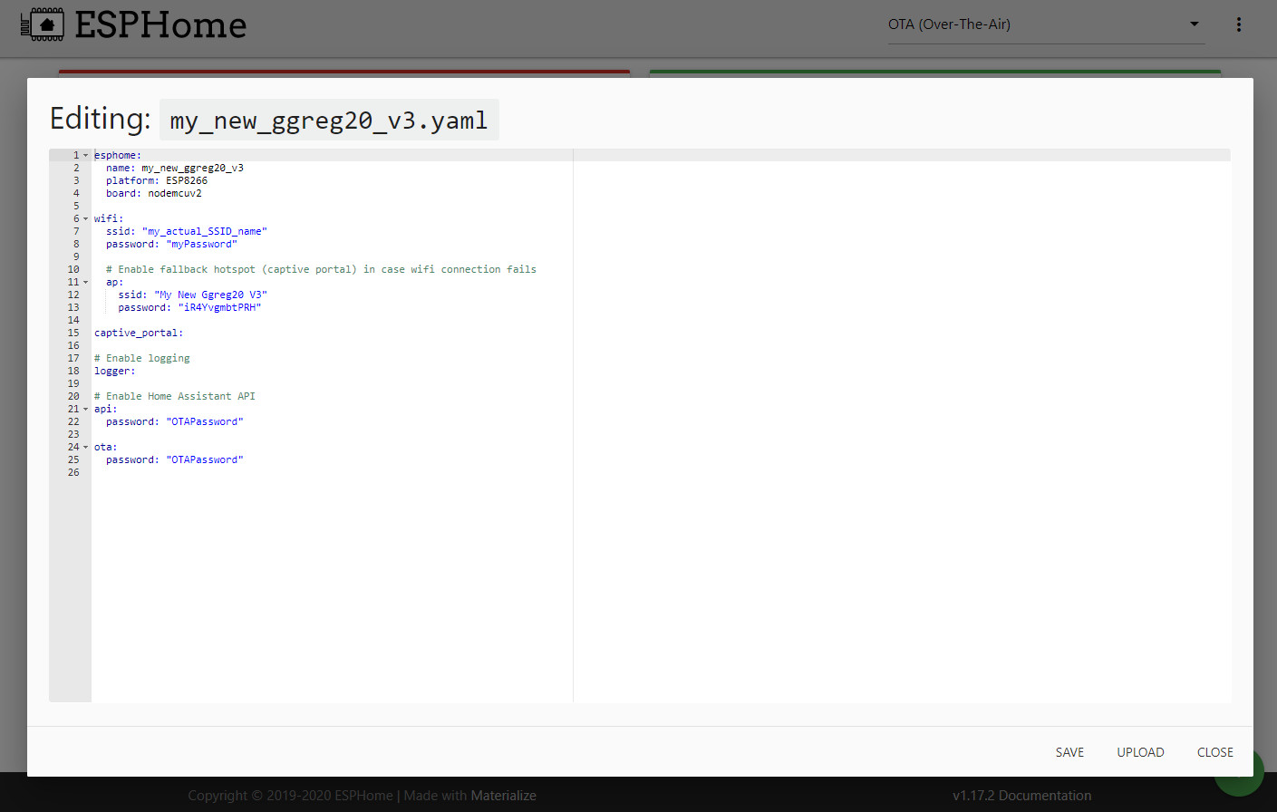
Fig. Basic configuration for ESP8266 / NodeMCU created by the “wizard”.
For example, here is a similar initial yaml file for ESP32. As you can see, it is almost no different from the file for ESP8266.
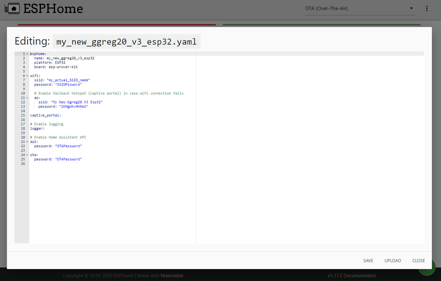
Fig. Basic configuration for ESP32 / WROVER that creates a “wizard”.
If you compile the firmware with such an initial file – it will work and do the basics – connect to the server, raise the access point for settings and so on. But such a controller will not perform any application tasks.
That’s why you need the file we developed – you need to copy the rest of the settings from our file to yours. You can also completely replace the contents of your file with data from ggreg20_esp8266_esphome.yaml, of course, if you have an ESP8266 controller. If you have a different controller – you need to replace the relevant parts of the file, and leave the rest unchanged.
Conclusions
We’ve completed the following steps to connect GGreg20 to Home Assistant:
Step 1. Install (or start) the Home Assistant server
Step 2. Connect the ESP Home extension for the Home Assistant server via the Supervisor -> Add-on Store menu
Step 3. Download the ready example of a batch yaml-configuration file of the GGreg20_V3 device for ESP8266 from our website
Step 4. Create (based on the example) in ESP Home the appropriate yaml configuration file
Next, we consider the following steps in detail:
Step 5. Select the GPIO pin on the controller that will register the pulses from GGreg20
Step 6. Connect the GGreg20_V3 radiation detector to the ESP8266 controller via the Out connector to the selected GPIO of the controller
Step 7. Build and write firmware for the controller
Step 8. Check the log of the new ESP8266 controller with Ggreg20 connected
Step 9. Check for new entities on the server side
Step 10. Add Ggreg20 radiation sensor widgets to Dashboard
Step 11. Add a Push Notification Automation script to the Home Assistant Threshold Crossing app
That’s all. We wish you success!