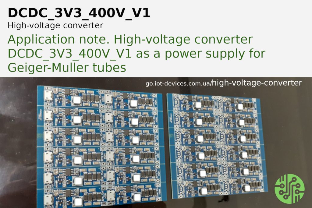
The DCDC_3V3_400V_V1 module is a high voltage source for powering a wide range of Geiger-Muller tubes with different anode-cathode voltage levels, and can also be used as a low-power high voltage source in other DIY projects.
The need to set different output voltage levels is one of the reasons for installing a tuning potentiometer in the module.
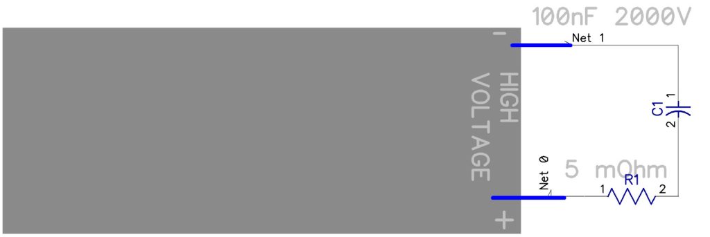
The other adjustment components are resistor R1 and capacitor C1.
For explanation, please see the block diagram below.
The left part of the block diagram shows the structure of the high-voltage converter DCDC_3V3_400_V1 module.
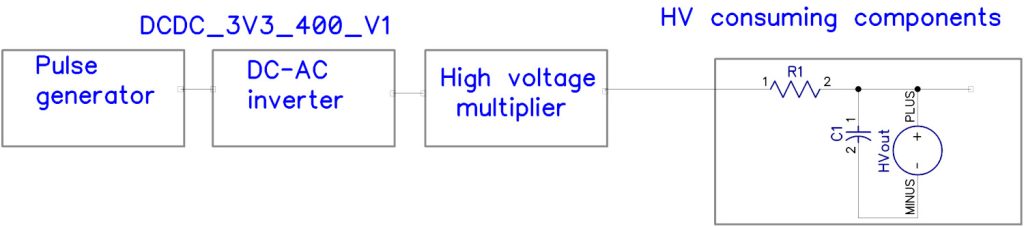
The right part of the block diagram shows the components of the power consumers from the DCDC_3V3_400_V1 module integrated into the DIY project, according to the user’s design.
The output cascade of the DCDC_3V3_400_V1 module is a high-voltage multiplier. In projects of radiation detectors based on the Geiger-Muller counter, the tube receives a high voltage of 300 to 2000 volts through the R1C1 circuit.
The resistance, capacitance and voltage values for R1 and C1 depend on the type of tube or DIY circuitry. For this reason, R1 and C1 are not installed on the DCDC_3V3_400_V1 module.
Another reason for the absence of R1 and C1 on the module is the possibility of damage (electrical breakdown) of C1 when adjusting the voltage with a potentiometer.
Taking these factors into account, we recommend that when testing the DCDC_3V3_400_V1 module, you solder or connect a circuit to the output contacts according to the following scheme:
The voltage adjustment and measurement should be performed similarly to the steps described in the Initial Diagnostics Manual for the Geiger counter module GGreg20_V3.