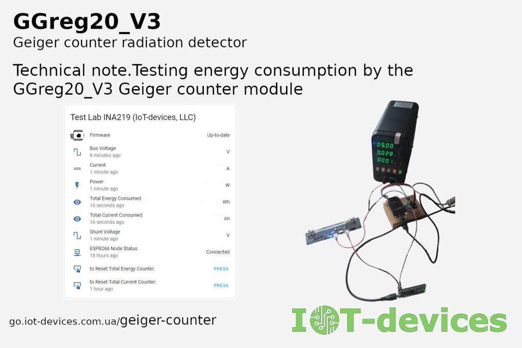
Our company has conducted a thorough testing of the power consumption of the Geiger counter module GGreg20_V3, intended for use in DIY projects. The purpose of the study was to determine the real power consumption of the module at different supply voltages: 3.3V, 3.7V, 5.0V.
Testing methodology
To conduct the measurements, we developed a special test bench based on the Home Assistant platform. The central element of the system was the Raspberry Pi Pico W controller with ESPHome firmware, which controlled the operation of the GGreg20_V3 module. To accurately measure the energy consumption, we used an INA219 sensor connected to a NodeMCU/ESP8266 controller also running ESPHome firmware. We used a laboratory power supply as a power source for the GGreg20_V3, which set the exact voltage level during testing.
Since the GGreg20_V3 module supports a wide range of supply voltages, from at least 3.0V to 5.5V, we used the three most common supply voltage levels to show how the test result differs: 3.3V, 3.7V, 5.0V. These voltages give us an idea of the module’s consumption when powered by:
- another controller or source with a voltage of 3.3V;
- a 3.7V lithium battery;
- another controller or source with a voltage of 5V.
It is important to note that the INA219 sensor measured only the power consumption of the GGreg20_V3 module, while the controllers were powered separately. This allowed us to obtain the most accurate data.
Also note that the supply voltage level did not change over time during the 60-minute test. Therefore, you should not expect that we have performed a complete emulation, for example, of a lithium battery that discharges under load and, accordingly, loses voltage from 4.2V to 2.5V during the test. Although this would have been a really useful and interesting experiment, we decided not to bother with it that much.
Test bench
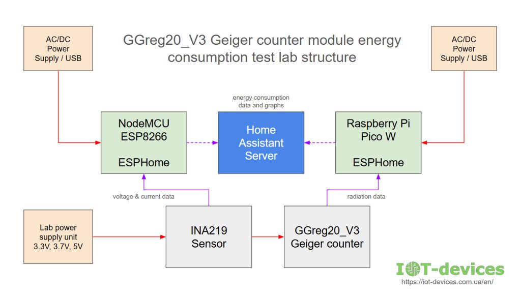
| Component | Purpose | Power supply | Firmware / Interface |
|---|---|---|---|
| GGreg20_V3 | The object of study of energy consumption; Measurement of radiation level | via INA219 from the laboratory power supply | – / GPIO output, Active-Low |
| Raspberry Pi Pico W | Receiving data from the GGreg20_V3 module and transferring it to the Home Assistant server | USB | ESPHome with configuration for GGreg20_V3 as sensor / WiFi wireless connection |
| INA219 | Measurement of current consumption by the GGreg20_V3 module | from the laboratory power supply unit | – / I2C |
| NodeMCU ESP8266 (or ESP12_OLED) | Controlling the INA219 module, receiving measurement data, and transmitting it to the Home Assistant server | USB | ESPHome with configuration for INA919 as sensor / WiFi wireless connection |
| Lab power supply unit | Supply the INA219 and GGreg20_V3 sensor modules with the set voltage | 220V power mains | DC output 3.3V, 3.7V, 5.0V. |
| Home Assistant server | Enables data transfer between devices via WiFi; Collection, processing and visualization of measurement data | 220V power mains | wireless WiFi connection |
Software on the side of the measuring sensor of consumed electric energy based on ESP8266 + INA219 with ESPHome firmware:
sensor:
 - platform: ina219
 address: 0x40
 shunt_resistance: 0.1 ohm

 current:
 name: "INA219 Current"
 accuracy_decimals: 5
 id: current_value

 power:
 name: "INA219 Power"
 accuracy_decimals: 5
 id: power_value

 bus_voltage:
 name: "INA219 Bus Voltage"
 accuracy_decimals: 5

 shunt_voltage:
 name: "INA219 Shunt Voltage"
 accuracy_decimals: 5

 max_voltage: 32.0V
 max_current: 3.2A
 update_interval: 1min

 - platform: integration
 name: "Total Energy Consumed"
 id: total_energy
 sensor: power_value
 time_unit: min
 accuracy_decimals: 5
 unit_of_measurement: "Wh"
 filters:
 - multiply: 0.0166666666666667

 - platform: integration
 name: "Total Current Consumed"
 id: total_current
 sensor: current_value
 time_unit: min
 accuracy_decimals: 5
 unit_of_measurement: "Ah"
 filters:
 - multiply: 0.0166666666666667
This YAML configuration snippet provides all the necessary data for our planned testing of the GGreg20_V3 radiation sensor module in terms of power consumption during operation under normal background radiation conditions.
Measurement process
The power consumption was measured every minute, with data accumulated for previous periods. The test lasted for an hour, which allowed us to obtain the real consumption of the GGreg20_V3 module for 60 minutes for each of the three supply voltages.
The Home Assistant platform was used to collect and record sensor data. It also provided tools for creating visual graphs of electricity consumption.
Results and conclusions
Thanks to the testing, we have obtained detailed data on the power consumption of the GGreg20_V3 module at different supply voltages. These results allow users to optimize the power consumption of their DIY projects using this module.
Power supply with a voltage of 3.3V


Power supply with a voltage of 3.7V


Power supply with a voltage of 5.0V


Summary of results
The power consumption of the GGreg20_V3 module was tested for 60 minutes at different voltages under normal conditions. INA219 measurement update cycle: 1 minute
| 5 Volts | 3.7 Volts | 3.3 Volts | |
|---|---|---|---|
| Output voltage of the laboratory PSU, V | 5,11 | 3,83 | 3,45 |
| Supply voltage of the GGreg20_V3 (on the INA219 sensor), V | 5,01 | 3,7 | 3,32 |
| Power consumption during the test (LED blinks, buzzer beeps), A*h | 0,03523 | 0,05174 | 0,05741 |
| Instantaneous current at rest, A | 0,0343 | 0,04880 | 0,05664 |
| Peak bursts of instantaneous current (blink & beep, duration 10 ms), A | 0,051 | 0,064 | 0,093 |
Test dates: 27.08. – 31.08.2023
No deviations in radiation level measurements were observed during testing
Testing was performed in the default settings of the GGreg20_V3 module. The buzzer is enabled. The Schottky protection diode is installed. Blue power supply LED lights constantly. The supply voltage remained unchanged throughout the test cycle.
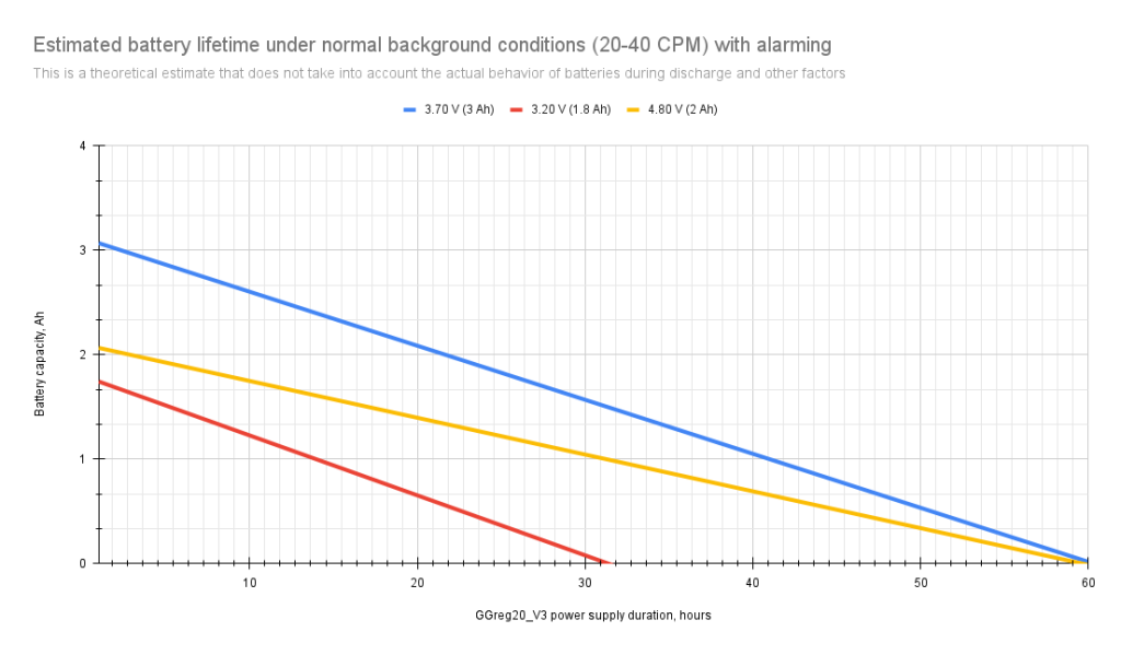
Appendix. Theoretical battery discharge diagram
We also decided to show the theoretical discharge graph at three different voltages when the GGreg20_V3 module is powered by batteries of different chemistry and capacity.
The basis for our calculations was the battery characteristics available on the Internet:
| Battery voltage level | Battery assembly | Example of a rechargeable battery |
|---|---|---|
| 3.2V | 1 х | Soshine 18650 1800 mAh LiFePO4 3,2В |
| 3.7V | 1 х | Sony 18650 VTC6 3.7V 3120 mAh (30А) |
| 4.8V | 4 х in series | Videx NiMH AA HR6 1.2V 2100 mAh |
However, please note once again that this graph is a theoretical assumption and does not take into account the discharge of real batteries under load over time and changes in voltage and current consumption during discharge.
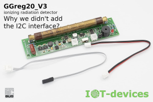
About GGreg20_V3
The Geiger counter module GGreg20_V3 manufactured by IoT-devices, LLC is the company’s flagship product, which has found its users in more than 30 countries.
All over the world, radio amateurs use GGreg20_V3 to create their own DIY projects, learn and conduct experiments related to radiation measurement.
When developing this product and improving it since 2020, we tried to make the module compact, ready-to-use, compatible with as many DIY platforms and systems as possible, undemanding in terms of power supply voltages, easy to program, and harmonized in terms of operating characteristics with various Geiger tubes.
We have also developed a number of examples and posted them on GitHub for various hardware and software platforms such as Arduino UNO, ESP32, ESP8266, Raspberry Pi Pico W, NodeMCU, ESPHome, Tasmota, MicroPython, Home Assistant.
And we, at IoT-devices Company, hope that our Customers will have a great user experience and real pleasure by implementing this module in their projects.
We also thank everyone for supporting and choosing this product designed and manufactured in Ukraine. We really appreciate it!
Keywords
Geiger counter
GGreg20_V3
Testing of energy consumption
DIY-projects
Home Assistant
Raspberry Pi Pico W
ESPHome
INA219
NodeMCU
ESP8266
I2C
WiFi
YAML