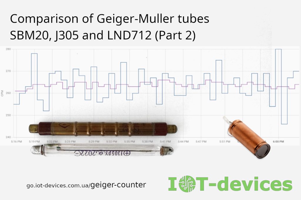
In the first part of our material, we examined the general specifications and applications of popular sensors: SBM-20 (SBM20), J305, and LND712.
This second part is an attempt to dive into the internal geometry of the tubes, estimate their actual effective volume and cathode area, build a mathematical model to evaluate their Dead Time, and clear up the blind spots and myths surrounding their specifications.
A particularly valuable data source for us came from simulations provided by the open-source engineering project Rad Lab (by Gissio). Using the Geant4 toolkit—a Monte Carlo framework for simulating the interaction of particles with matter—the project performed physical modeling for the SBM20 and J305 tubes.
Unfortunately, the Rad Lab materials currently lack dataset information for the LND712 tube; therefore, we will apply our own analytical calculations and comparative analysis to evaluate it.

Disclaimer from the authors: We are not a research institute, a metrology laboratory, or ultimate experts in nuclear physics. We are practicing engineers and IoT development enthusiasts. All calculations, mathematical models, and conclusions presented below represent our hypotheses, analytical assumptions, and attempts to explain physical processes based on open data and computer simulations. We are always open to constructive discussion.
Geometric Calculation: Effective Cathode Area and Working Volume
The generally accepted theory states that the sensor’s sensitivity to gamma and beta radiation depends on two main geometric factors:
- Inner surface area of the cathode A_in — determines the probability of secondary electron emission under the action of gamma quanta.
- Working gas volume V_in — determines the ionization path length and the stability of the gas discharge.
To perform the estimation, we will apply the basic formulas for a cylinder:
- Internal diameter: D_in = D_out – 2*t (where t is the wall thickness)
- Internal radius: r_c = D_in / 2
- Cathode area estimation: A_in = PI * D_in * L_eff
- Working volume estimation: V_in = PI * (r_c^2) * L_eff
Refined geometry parameters (including data from Rad Lab / Geant4 simulations):
If you look purely at the external dimensions, it might seem that the SBM-20 is significantly larger than the J305. However, analyzing the precise models from the Rad Lab project reveals the real picture:
SBM20:
- Massive bakelite end caps significantly reduce the active area.
- Effective working length: L_eff ~ 6.99 cm (69.9 mm).
- Inner radius of the cathode: r_c = 4.95 mm (casing — stainless steel, density 8.0 g/cm3).
Effective area A_in ~ 21.72 cm2
Effective volume V_in ~ 5.37 cm3
J305 (J305beta/gamma):
- The design of the tube allows for efficient use of almost the entire length of the glass.
- Effective working length: L_eff ~ 8.20 cm (82.0 mm).
- Inner radius of the cathode: r_c = 4.48 mm.
- Cathode material: tin oxide coating (Tin Oxide / SnO2) with a thickness of ~ 20 µm (density 6.95 g/cm3) on the inner wall of borosilicate glass.
Effective area A_in ~ 23.08 cm2
Effective volume V_in ~ 5.17 cm3
LND712 (End-window, analytical assessment):
- D_out = 9.10 mm | t ~ 0.30 mm (steel) | L_eff ~ 38.1 mm
- D_in = 8.50 mm (r_c = 4.25 mm)
- Lateral area = 10.17 cm² | Area of the end mica window = 0.57 cm²
Area A_in (total) ~ 10.74 cm²
Volume V_in ~ 2.16 cm³
Why does the J305, according to documentation and in practice, exhibit sensitivity comparable to that of the SBM-20?
Visually, the SBM-20 appears more massive than the Chinese J305, and it is often assumed that it must have a significantly higher background count.
However, the J305 datasheet lists the background reading as 25 CPM under natural background conditions (~0.1 μSv/h). Many users in the community confirm that actual units produce exactly these readings, which are virtually identical to those of the SBM-20 (~22–29 CPM).
These Rad Lab simulations provide a clear mathematical explanation for this parity:
- Identical Working Volumes: Thanks to the J305’s greater effective chamber length (82 mm versus 69.9 mm for the SBM-20), its effective gas volume is 5.17 cm³, which differs by less than 4% from that of the SBM-20 (5.37 cm³).
- Tin oxide compensation: The J305 cathode is made of tin oxide (SnO₂). Tin’s high atomic number (Z = 50) compensates for the transparency of borosilicate glass to gamma rays through the efficient generation of photoelectrons, thanks to which the effective area of the J305 cathode (23.08 cm²) even slightly exceeds that of the SBM-20 (21.72 cm²).
- Identical gas: The simulation confirms that both sensors use the same Penning gas mixture (Ne + Ar + Br2).
Engineering Conclusion: A single J305 tube on its own may be quite sufficient for a full-fledged DIY project. However, if we combine an array of two or more parallel J305 tubes, we obtain a total active cathode area of ~46.16 cm² and a volume of ~10.34 cm³. This allows us to build a device that is comparable in quality and statistical reliability of data to professional instruments.
The Hidden Physics of Interactions: What the Geant4 Simulation Reveals (Rad Lab)
Thanks to Geant4 simulations from the Rad Lab project, we can go beyond the specifications and observe processes that are usually overlooked:
A. What exactly detects gamma rays?
There is a theory that the gas inside the tube absorbs gamma rays. Simulations show that over 90–95% of the discharges occur not because the gas is ionized by a gamma ray, but because the gamma ray knocks an electron out of the inner wall of the cathode (made of steel in the SBM-20 or SnO₂ in the J305), and it is this electron that triggers the ionization avalanche. A Geiger counter for gamma radiation is, in fact, an emission-type device, where the gas serves only as an amplification medium.
B. Beta-particle sensitivity threshold (Beta Cut-off)
- SBM-20 (steel ~ 0.05 mm): Transmits beta particles (electrons) with energy from approximately 150-200 keV.
- J305 (glass + SnO₂): Due to the higher density of the glass wall, the cutoff threshold is slightly higher—250–300 keV.
A practical consideration: The SBM-20 may exhibit slightly higher sensitivity to soft beta radiation than the J305.
С. Spectral Energy Response
The J305 glass wall with tin oxide transmits “soft” low-energy gamma radiation (< 50 keV) better than the SBM-20 steel wall. Thanks to its steel construction, the SBM-20 provides better shielding against low-energy radiation, blocking background interference.
D. Anisotropy and orientation within the case
A simulation of angular dependence shows that, under end-face irradiation (along the tube axis), sensitivity can decrease by a factor of 3 to 5 due to self-absorption of radiation in the bases and the thick walls of the cylinder.
Engineering tip: All tubes in the dosimeter should be positioned parallel to the instrument’s front panel, rather than with their ends facing the source.
An Analysis of the Myth Regarding the J305’s Sensitivity to UV Light
Several persistent stereotypes have emerged on amateur websites regarding the J305, which prevent developers from considering it as an alternative to the SBM-20.
Myth: The J305 glass flask reacts to sunlight and ultraviolet light (UV sensitivity)
The gist of the statement: “The J305 is made of glass, so when exposed to direct sunlight, UV photons knock photoelectrons out of the inner coating, causing the tube to ‘crack’ falsely and emit hundreds of false pulses.”
Physical Reality and Practice:
- Photoelectron emission work function: The tin oxide (SnO₂) semiconductor layer has an emission work function of approximately 4.8–5.0 eV, while the borosilicate-sodium glass of the flask completely blocks hard ultraviolet radiation with wavelengths shorter than 300–320 nm. Solar UV radiation reaching the Earth’s surface (UV-A and UV-B) does not have sufficient quantum energy to induce the photoelectric effect on the internal cathode.
- Parasitic current: False pulses caused by sunlight can only occur when direct light hits the tube contacts under conditions of high dust or humidity (due to leakage current), or if the high-voltage converter board contains exposed photosensitive elements.
- Design Solution: In an actual dosimeter or IoT module, the tube is housed inside an opaque casing or under a protective black heat-shrink sleeve. When covered with black J305 heat-shrink tubing, it is completely isolated from light and shows no sensitivity to radiation in the optical spectrum.
An Analysis of the Myth Surrounding the “Magical” Coefficients of 0.0057 and 0.0054 for Converting CPM to μSv/h for the SBM-20
Another common misconception in amateur dosimetry is the use of fixed conversion factors for converting count rate (CPM, counts per minute) to equivalent dose rate (μSv/h). In hundreds of Arduino sketches, GitHub projects, and forum posts for the SBM-20 and J305 tubes, the following formula is provided by default:
Dose (μSv/h) = CPM × 0.0057
Or its “improved” version with a multiplier of 0.0054. However, any attempt to derive these values from the official technical specifications of the unprotected SBM-20 tube immediately reveals their mathematical and metrological groundlessness.
Where did these numbers actually come from?
The coefficient 0.0057 is simply the reciprocal of a sensitivity of 175 CPM at a radiation dose rate of 1 μSv/h:
K = 1 / 175 ≈ 0.005714
Similarly, the factor of 0.0054 is obtained by dividing one by 185 CPM:
K = 1 / 185 ≈ 0.005405
The original source for the 0.0057 constant in 2011 was a library for the popular Radiation Sensor Board from Libelium (the Cooking Hacks project). The developers used the sensitivity value from the documentation for the Chinese J305 tube (175 CPM per 1 μSv/h for Cs-137), but specified it in the code as a universal coefficient for all SBM-20-type sensors.
On amateur radio forums (notably Dangerous Prototypes and EEVblog), attempts were later made to justify this value through a makeshift “calibration” against household dosimeters (such as the “Terra-P”). With a natural background radiation level of ~0.12 μSv/h, the open tube read about 22 CPM, which, when simply divided (22 / 0.12 ≈ 183.3), was rounded to 185 CPM (0.0054).
“Inverse transformation” error in units
In addition to copying the Libelium code, there is another mathematical pitfall that developers often fell into when attempting to convert the SBM-20’s passport data into a coefficient for the microcontroller on their own: an arithmetic error in the direction of division when converting between seconds and minutes.
An example of a possible calculation error:
- According to the specifications, the sensitivity of the SBM-20 to cobalt-60 (Co-60) is approximately 29 impulses per microR (per second).
- The author of the calculation is trying to determine how many pulses per minute (CPM) the tube will produce at 1 μSv/h (100 μR/h).
- Instead of converting hours to minutes by dividing by 60, the developer mistakenly multiplies or divides the initial second sensitivity (29 pulses/s) by a factor of 6 (resulting in 29 × 6 = 174 pulses) or attempts to use an outdated biological equivalent factor.
- After obtaining an incorrect figure of ~174–175 CPM per 1 μSv/h, he divides 1 by 175 to arrive at the “ideal” value of 0.0057.
As one participant in the discussion on the EEVblog forum aptly noted:
“0.0057 is a radiation-related internet meme. One person made a mistake in the Arduino code back in 2011, and everyone else just copied it into their own projects because no one wanted to open the SBM-20 manual and do the calculation correctly.”
Precise design calculations for the SBM-20
According to the official SBM-20 data sheet, the tube’s sensitivity to gamma radiation from a cesium-137 (Cs-137) source is specified as follows:
- In terms of counting rate: 240–280 counts per second at a dose rate of up to 4 μR/s.
- Based on the accumulated dose: 60–70 imp/μR (average value — 65 imp/μR).
Let’s perform a rigorous conversion of these values to the SI system (Sieverts)
- Assuming a conversion factor for gamma radiation of 1 μSv/h = 100 μR/h, we find that, over the course of 1 hour, with a background radiation level of 1 μSv/h, the tube will accumulate a dose of 100 μR.
- The total number of pulses per hour will be: 65 pulses/μR × 100 μR = 6,500 pulses.
- The count rate per minute (CPM) at a dose of 1 μSv/h is equal to: CPM = 6,500 counts / 60 min ≈ 108.33 CPM.
Therefore, the calculated coefficient K for the open SBM-20 tube is:
K_real = 1 / 108.33 ≈ 0.00923
Note: In our technical note, we round this ratio, and therefore find that 108 CPM = 1 μSv/h. Consequently, the conversion factor is 0.00926.
Engineering Conclusion: Using the “borrowed” coefficients of 0.0057 or 0.0054 for the open SBM-20 tube results in an artificial underestimation of the readings by nearly 1.7 times compared to the design calculations.
A reading of 175–185 CPM (0.0057–0.0054) can correspond to the SBM-20 only if a thick lead-brass compensation filter is used, which blocks soft radiation and beta particles. For a clean open tube in a Cs-137 field, a value of 0.0092 is mathematically justified.
Modeling Dead Time
The dead time (tau) is the period after discharge during which the tube is “blind” due to the anode being shielded by a slowly moving cloud of positive ions.
The main contribution to the tau time comes from the drift time of the positive ion core from the anode (r_a) to the critical radius r_crit, where the electric field strength returns to the Geiger discharge threshold.
A. Mathematical Model of Ion Drift
The electric field intensity in a coaxial cylinder at a distance r from the axis is given by the formula:
E(r) = V / (r * ln(r_c / r_a))
Where:
- V — operating voltage (V);
- r_a — radius of the anode wire (cm);
- r_c — inner radius of the cathode (cm).
The ion drift velocity v(r) is proportional to the electric field strength: v(r) = mu * E(r), where mu is the mobility of ions in the gas mixture (cm²/(V·s)).
Since v(r) = dr / dt, we obtain the following differential equation:
dr / dt = mu * V / (r * ln(r_c / r_a)) => r * dr = (mu * V / ln(r_c / r_a)) * dt
By integrating from r_a to r_c, we obtain the total time it takes for the ions to reach the cathode:
tau ~ ((r_c^2 – r_a^2) * ln(r_c / r_a)) / (2 * mu * V)
B. Determination of the gas mixture constant (mu) using the SBM-20 reference point
All three tubes use self-extinguishing gas mixtures based on neon, argon, and bromine vapor (Penning gas). Since the effective mobility of bromine ions (Br2+) depends on partial pressure, we can calculate the coefficient 2 * mu based on the specified value for the SBM-20 (tau_SBM20 = 190 μs):
Input data for SBM-20:
- r_c = 0.495 cm
- r_a = 0.075 cm (based on Rad Lab simulation data, d = 1.5 mm)
- V = 400 V
- tau = 1.9 * 10^-4 s
Calculation of the geometric factor for SBM-20:
- r_c^2 – r_a^2 = 0.495^2 – 0.075^2 = 0.245025 – 0.005625 = 0.2394 cm2
- ln(r_c / r_a) = ln(0.495 / 0.075) = ln(6.6) ~ 1.8871
- Numerator = 0.2394 * 1.8871 ~ 0.45177 cm²
Let’s find the denominator 2 * mu * V:
2 * mu * V = 0.45177 cm² / (1.9 * 10⁻⁴ s) ~ 2377.7 cm²/s
This yields an effective ion mobility of mu ~ 2377.7 / (2 * 400) ~ 2.97 cm²/(V·s), which is consistent with experimental data for Br₂⁺ ions in a neon medium at a pressure of ~ 100–120 mm Hg.
С. Calculation of the dead time for the J305 and LND712
Using the calculated value of the proportionality constant, 2 * mu ~ 5.944 cm²/(V*s), let’s substitute the geometric parameters of the other tubes:
1. J305 Tube (J305beta/gamma)
Parameters:
r_c = 0.448 cm,
r_a = 0.0375 cm (thinner anode d = 0.75 mm),
V = 400 V.
Step 1 (Geometry): r_c^2 – r_a^2 = 0.448^2 – 0.0375^2 = 0.200704 – 0.001406 = 0.1993 cm²
Step 2 (Logarithm): ln(0.448 / 0.0375) = ln(11.9467) ≈ 2.4805
Step 3 (Numerator): 0.1993 * 2.4805 ≈ 0.49436 cm²
Step 4 (Denominator): 2 * mu * V = 5.944 * 400 = 2377.7 cm²/s
Result:
tau_J305 = 0.49436 / 2377.7 ~ 2.079 × 10⁻⁴ s ~ 208 μs
(Thanks to the anode wire being half as thick, the logarithmic field factor increases, resulting in a calculated dead time of 205–210 μs.)
2. LND712 End Tube
Parameters:
r_c = 0.425 cm,
r_a ~ 0.005 cm (microanode d = 0.1 mm),
V = 500 V (elevated operating voltage).
Step 1 (Geometry): r_c^2 – r_a^2 = 0.425^2 – 0.005^2 = 0.180625 – 0.000025 = 0.1806 cm²
Step 2 (Logarithm): ln(0.425 / 0.005) = ln(85) ≈ 4.4426
Step 3 (Numerator): 0.1806 * 4.4426 ≈ 0.8023 cm²
Step 4 (Denominator, assuming V = 500 V): 2 * mu * V = 5.944 * 500 = 2972 cm²/s
Conclusion:
Taking into account the accelerated charge dissipation near the microanode and the increased voltage, the net period for complete threshold recovery is:
tau_LND712 ~ 88.5 μs
Note: Our theoretical calculation for the LND712 (88.5 µs) matched almost perfectly with
the manufacturer’s official specification limit (90 µs).
D. Summary Comparison Table
| Model | Cathode radius (rc) | Anode radius (ra) | Voltage (V) | Numerator | Calculated Dead Time | Datasheet Dead Time |
|---|---|---|---|---|---|---|
| SBM-20 | 4.95 mm | 0.750 mm | 400 V | 0.4518 cm² | 190 us (base) | 190 us |
| J305 | 4.48 mm | 0.375 mm | 400 V | 0.4944 cm² | 208 us (calc) | Not defined in datasheet |
| LND712 | 4.25 mm | 0.050 mm | 500 V | 0.8023 cm² | 88.5 us (calc) | 90 us (Max) |
Additional Facts About the J305 Specification
Many reviews often cite specific Dead Time values for the J305, presenting them as official data.
Official fact: In the manufacturers’ factory specifications (Beijing Nuclear Instrument, North Pipe, etc.), the “Dead Time” parameter is NOT listed for the J305.
Manufacturers specify only the plateau, operating voltage, and background count (25 CPM). Any figures in the range of 150–210 μs are either results from theoretical models or empirical measurements of individual units.
Practical Analysis of an Oscillogram: Physical Dead Time J305 and Electrical RC Relaxation
To verify the theoretical calculations, an oscillogram of the actual discharge pulse from tube J305 at the output of the GGreg20_V3 module was recorded. The measurements were taken directly across the cathode load resistor R_cat = 10.4 MΩ, connected between the cathode (negative terminal) and ground (GND).
Scan parameters: 200 µs/division on the time axis (X) and 100 V/division (X10 DC) on the voltage axis (Y).
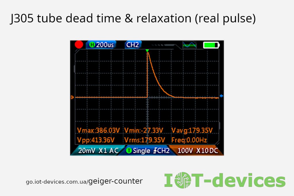
Analysis of the oscillogram shows that the observed signal, lasting approximately 500–600 μs, is the result of the sequential superposition of two fundamentally different processes: the physical drift of the ion cloud inside the tube and the electrical RC relaxation of the cathode circuit.
1. Physical Process: Ion Drift and Formation Dead Time (τ)
- Steep rise front (t = 0): The nearly vertical rise in amplitude indicates an instantaneous electron avalanche (gas amplification) process that lasts a fraction of a microsecond.
- The first major segment of the screen (0–208 μs): Corresponds to the counter’s dead time (τ). During this time interval, heavy positive gas ions form a dense cloud around the anode filament, shielding its electric field. Until the ion shell has moved a sufficient distance away from the anode, no new ionizing particle is capable of causing a secondary breakdown (the amplitude of the secondary discharge is zero). For the J305 geometry and a voltage of 400 V, this physical period is calculated to be approximately 208 μs.
2. Electrical Process: RC Relaxation of the Cathode Circuit (Recovery Time)
Upon completion of the initial shielding, the recovery phase (Recovery Time) begins, overlaid by the purely electrical operation of the GGreg20_V3 module’s circuity:
- RC time constant (τ_rc): Since the 10.4 MΩ measuring resistor is located in the cathode circuit and the equivalent parasitic capacitance (comprising the tube, PCB traces, and oscilloscope input capacitance) is C_total ≈ 10 pF, the RC circuit time constant is: τ_rc = R_cat × C_total = 10.4 MΩ × 10 pF = 104 μs.
- Recovery phase (208–520 μs): As ions drift to the cathode wall, the electric field is restored, and the charge accumulated on the cathode circuit capacitance begins to drain through the 10.4 MΩ resistor to zero. According to the 3τ_rc rule (3 × 10⁴ μs = 312 μs), the circuit potential is restored by 95%. Together with Dead Time, this gives: t_work = τ_dead + 3τ_rc = 208 μs + 312 μs = 520 μs (~2.6 major divisions). At this point, the tube already has enough electric potential to stably record the next pulse.
- Complete decay (520–728 μs): According to the classical 5τ_rc rule (5 × 10⁴ μs = 520 μs), the signal completely decays to the baseline (99.3% relaxation). The total time for the circuit to completely settle is: t_total = τ_dead + 5τ_rc = 208 μs + 520 μs = 728 μs.
Engineering conclusion: The oscillogram clearly demonstrates that Dead Time (τ ~ 208 μs) is only a component of the overall sensor response time cycle (Recovery Time).
The use of a high-resistance cathode load (10.4 MΩ) in the GGreg20_V3 module ensures the formation of an amplitude-expressed pulse with a range of Vpp ~ 413.36 V, which guarantees reliable operation of the input comparator, and the duration of the decay tail strictly corresponds to the calculated mathematical model of RC relaxation.
Market realities and practical choices for the maker
When choosing a component for a production or DIY device, geometry and physics are only part of the factors. The rest are logistics, availability, and ethical considerations.
1. The Soviet SBM-20 is not an option for new developments:
- Lack of new quality stock: Most SBM-20 tubes on the market are old stock remnants (NOS) 30-40+ years old with a worn-out life and risk of gas mixture degradation.
- Origin and Sanctions: The SBM-20 was and is still manufactured in Russia, an aggressor country waging an aggressive war against Ukraine and subject to severe international sanctions. The purchase or use of such parts in new products is unacceptable for ethical, legal, and security reasons.
2. LND712 — a valuable tube for detecting alpha particles:
- The LND712 is a high-quality American tube; its high cost and logistics significantly increase the device’s production cost.
- In the DIY sector, its use is justified in specialized projects—for example, to detect household radon (a decay product of uranium), which emits alpha particles that are captured by the mica window.
3. J305 — a practical choice:
- The J305 tube is mass-produced at modern manufacturing facilities, is affordable, and has reliable delivery schedules.
- For a basic DIY project, a single J305 tube may be more than enough. Using multisensor arrays (2 or more J305 tubes) allows you to create a device with data quality and statistical accuracy comparable to professional instruments.
Thank you for your attention!
Read also
Geiger tube J305: How to calculate the conversion factor of CPM to μSv/h Technical note
Detector of radioactive particles GGreg20_V3 Geiger counter
Detector of radioactive particles GGreg20_V3 Geiger counter
Technical note: How to calculate the conversion factor for Geiger tube SBM20
Geiger-Muller tubes: Comparison of SBM20, J305 and LND712 (Part 1)
That’s all for now.
We hope you enjoy your DIY projects!