Before you begin
- The components of the device contain dangerous voltages. Do not violate safety precautions and rules for handling electrical installations.
- To maintain the warranty of the device, users are not allowed to adjust the potentiometer themselves. To make changes to the module settings, please first obtain authorization and instructions from the support team.
- Please note that if you use a conventional voltmeter (not the one required by this manual) to measure high voltage on the GGreg20_V3 module, the measurements will be inaccurate and insecure. Often, inaccurate measurement and adjustment leads to the device being inoperable or damaged.
Please do not attempt to measure high voltage with inappropriate tools.
A conventional voltmeter may show 150V, while the real voltage value may reach 500V, which is guaranteed to damage the module or tube. The multimeter can also be damaged.
Also, a conventional multimeter may not have the necessary speed to convert the analog values being measured.
And finally, note that high voltage measurements are performed on a capacitor, so do not forget to give it time to charge before the next measurement.
Getting started
1. Disconnect the module from the MCU board and provide power to the module via the corresponding connector on the module (BAT).
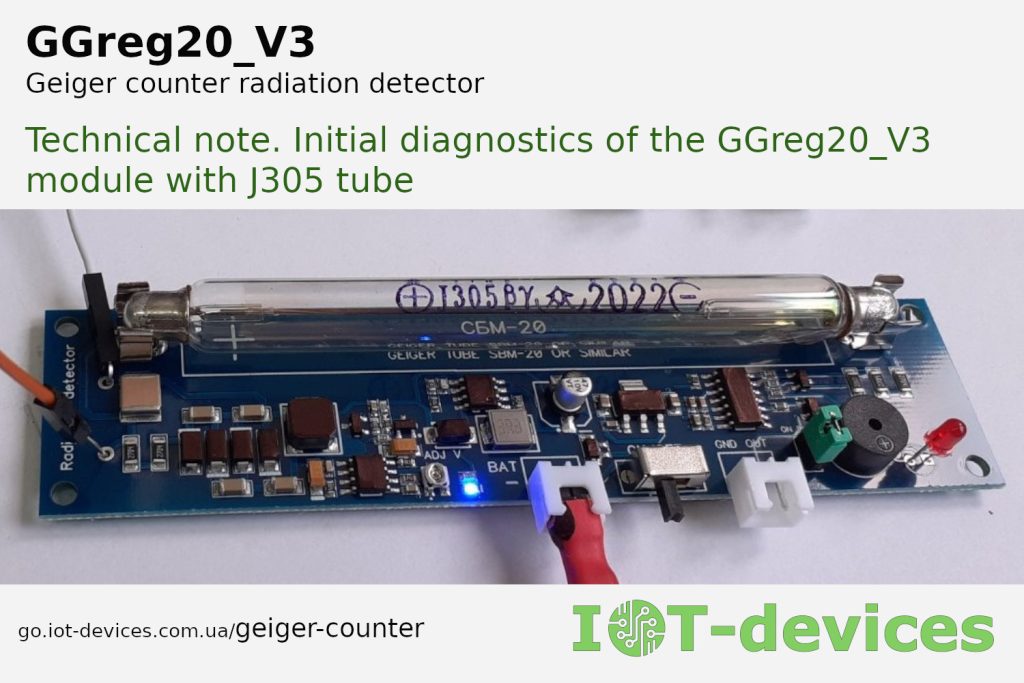
2. Inspect the detector board with a magnifying lens for damaged components.
3. Check the input DC power supply voltage Upower_supply that is supplied to the module. The input DC voltage must be between 3.0 and 5.5 V. The power supply must be at least 5 watts (1 amp at 5 V).
4. Check whether the J305 tube is properly mounted on the holders. Caution! The electrodes of the tube and some other components may contain dangerous voltages for a long time after switching off.
5. Turn on the GGreg20_V3 detector module without the case to access the diagnostic points.
6. The blue LED lights up normally.
7. The red LED does not blink (the buzzer does not beep, there are no pulses at the output, even with a jumper).
1. Tools needed
1. Oscilloscope with the following characteristics:
1.1. Measurement of the DC voltage level up to 500-600 volts.
1.2. The input impedance of the oscilloscope (probe) is not less than 10 MΩ.
1.3. Fixation (memorization, aka MIN/MAX) of the instantaneous maximum value of the DC voltage during measurement.
Note: Alternatively, a multimeter with the above characteristics can be used. However, an oscilloscope will be much more convenient for this task.
2. Diagnostic actions
Objective: to obtain data on voltages:
- on the module’s power supply points (low-voltage part);
- on the module’s elements of the high-voltage part.
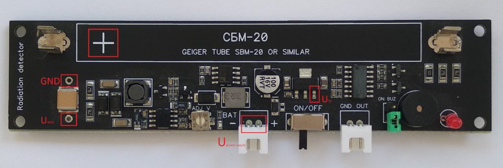
2.1 Diagnostic points
2.2 Low Voltage Measurement
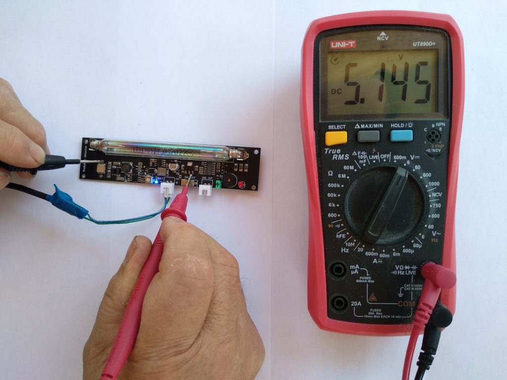
2.2.1 Make sure that the DC voltage level of U5V at the point shown in the Fig. is 5V +-5%.
2.3 High Voltage Measurement
2.3.1 Set up the oscilloscope and probe as follows:
– Select the input channel, set the mode to DC, 10 volts per division.
– Set the switch on the probe to the 1:10 position.
– Sampling rate (number of signal points per unit time): 1 division per 1 second.
– Set the function of fixing instantaneous maximum voltage values.
2.3.2 Carefully connect the oscilloscope’s GND pin to the module’s GND. To do this, point the GND pin (or solder a wire) to the point “GND” shown in the Fig. Measure the voltage level at the point shown in the Fig. with a probe.
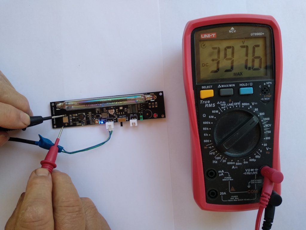
2.3.3 Make several measurements of U400V. Between measurements, pause for 5-10 seconds, which is necessary to restore the capacitor charge level. Observe on the oscilloscope screen the waveform of the capacitor discharge by the input resistance of the oscilloscope and the measured maximum voltage values. The correct voltage value should be as follows: 380 +- 40 volts for J305 tube.
Warning:
a) A voltage of 400 volts is dangerous to the human body.
b) Inaccurate positioning of the oscilloscope probe at the measurement point may cause damage to other components.
3. Observed Data Collection and Reporting
Please contact our support team with the measurement results (Upower_supply, U5V, U400V). We will provide additional instructions.