

Detector of radioactive particles GGreg20_V3 Geiger counter
1729.35грн. 3760.20грн.Price range: 1729.35грн. through 3760.20грн.
The GGreg20_V3 radioactive particle detector is an electronic sensor module for building a personal Geiger counter and determining the level of ionizing radiation. For this purpose, the detector includes an impulse counting output to a host controller. Arduino, Raspberry Pi, ESP8266, ESP32 and others can be used as a host controller.
The radiation level is indicated by light and sound signals. The user can mute sounds (jumper J1 – buzzer on/off).
GGreg20_V3 is an inexpensive and useful device for checking the “purity” of
- mushrooms,
- berries,
- vegetables,
- firewood, etc.
This module is useful for creating smart measurement devices for determining the power of ionizing radiation indoors or outdoors and is available in both portable/pocket style and stationary mode.
The only thing you need to start measuring ionizing radiation with the GGreg20 is any microcontroller that can count the number of pulses per unit time on GPIO.
Description
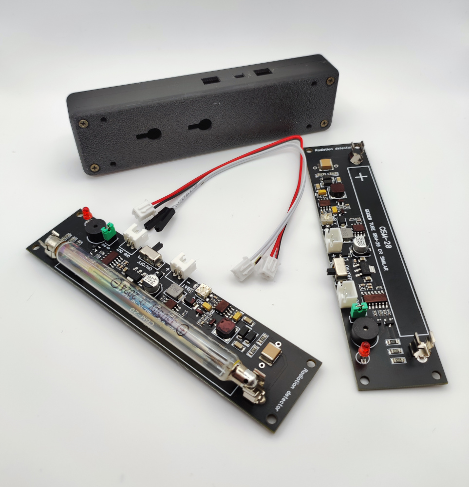
The ionizing radiation detector GGreg20_V3 is a ready-to-use new generation IoT device with a Geiger tube SBM-20 or J305 and a pulse counting output to the controller.
Purpose
The GGreg20_V3 radioactive particle detector is an electronic sensor module for building a personal Geiger counter and determining the level of ionizing radiation. For this purpose, the detector includes an impulse counting output to a host controller. Arduino, Raspberry Pi, ESP8266, ESP32 and others can be used as a host controller.
The radiation level is indicated by light and sound signals. The user can mute sounds (jumper J1 – buzzer on/off).
GGreg20_V3 is an inexpensive and useful device for checking the “purity” of
- mushrooms,
- berries,
- vegetables,
- firewood, etc.
This module is useful for creating smart measurement devices for determining the power of ionizing radiation indoors or outdoors and is available in both portable/pocket style and stationary mode.
The only thing you need to start measuring ionizing radiation with the GGreg20 is any microcontroller that can count the number of pulses per unit time on GPIO.
Specifications
- Module dimensions – 30 x 126 x 12 mm. Weight 30 g.
- Power supply:
- a rechargeable battery or a battery:
- 1-cell Li (3.7V) battery;
- 2-cell Ni (2.4V) battery;
- 3-cell 4.5V battery connected to the “Bat” port.
- a 5 Volt charger.
- Power supply of the SBM-20 tube is a built-in adjustable high voltage DC-DC converter. The target voltage level of 400 V is regulated by a potentiometer. The module is fine-tuned and ready for use.
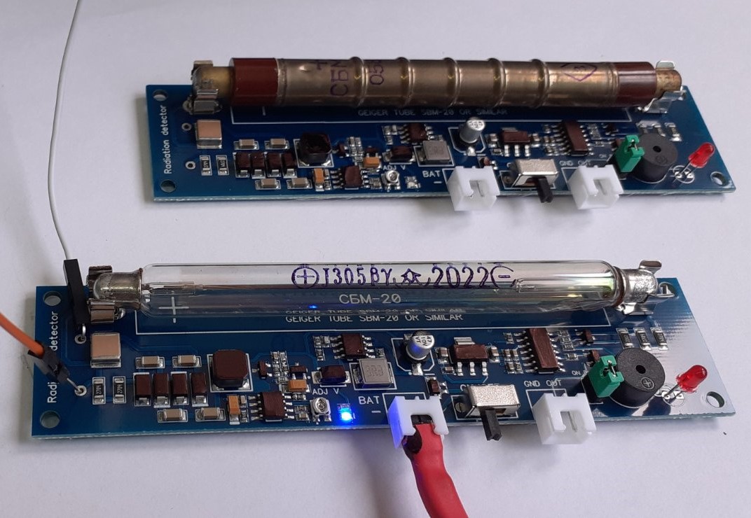
- The module also works with the J305 tube, and it is possible to choose a configuration with this tube when ordering.
Warning! From September 1, 2022 the high voltage regulation function has been removed. The hardware fixes the voltage level at 400 volts.
At the same time, if you need a module with increased voltage regulation for your project, pay attention to the DCDC_3V3_4000V_V1 module: високовольтний перетворювач напругиUpdate: February 2023 The feedback we receive from customers about the planned implementation of the changes has led us to the decision not to rush to fix the voltage level on the module, as this limits the possibility of using other tubes compatible with the module. Therefore, we have decided not to make any changes at all and are supplying the module in its original configuration.
- Consumption current – 35 mA at 5V, 52 mA at 3.7V or 57 mA at 3.3V.
- GGreg20_v3 is compatible with the ESP8266/ESP32 logic signal levels (3V3 ACTIVE-LOW: 3 to 3.3V HIGH and about 0.7V LOW), and will work even with the 5V logic input.
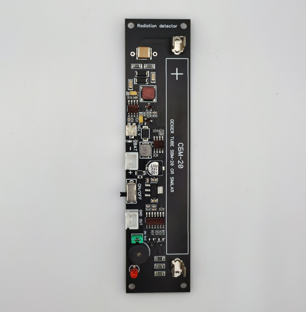
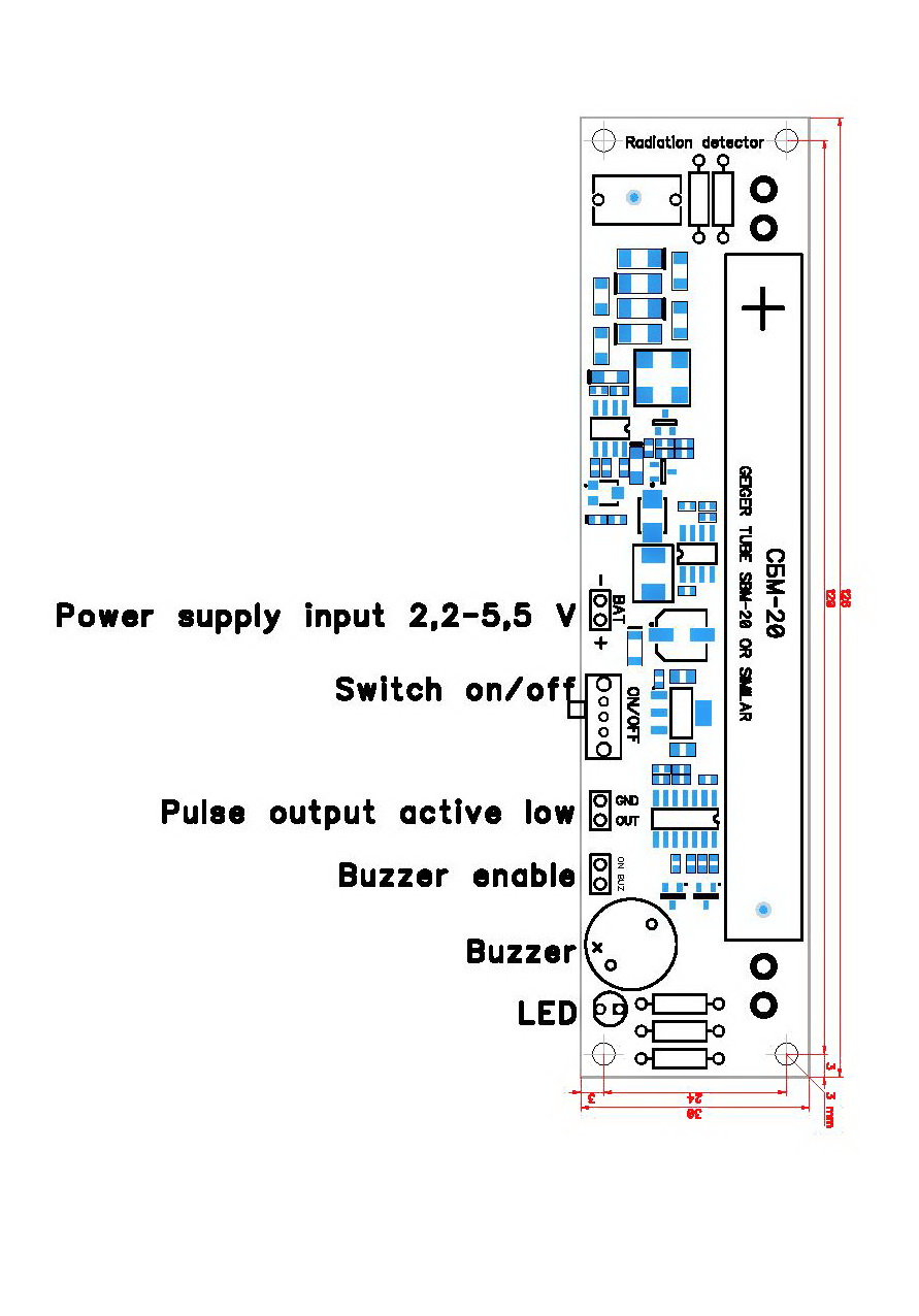
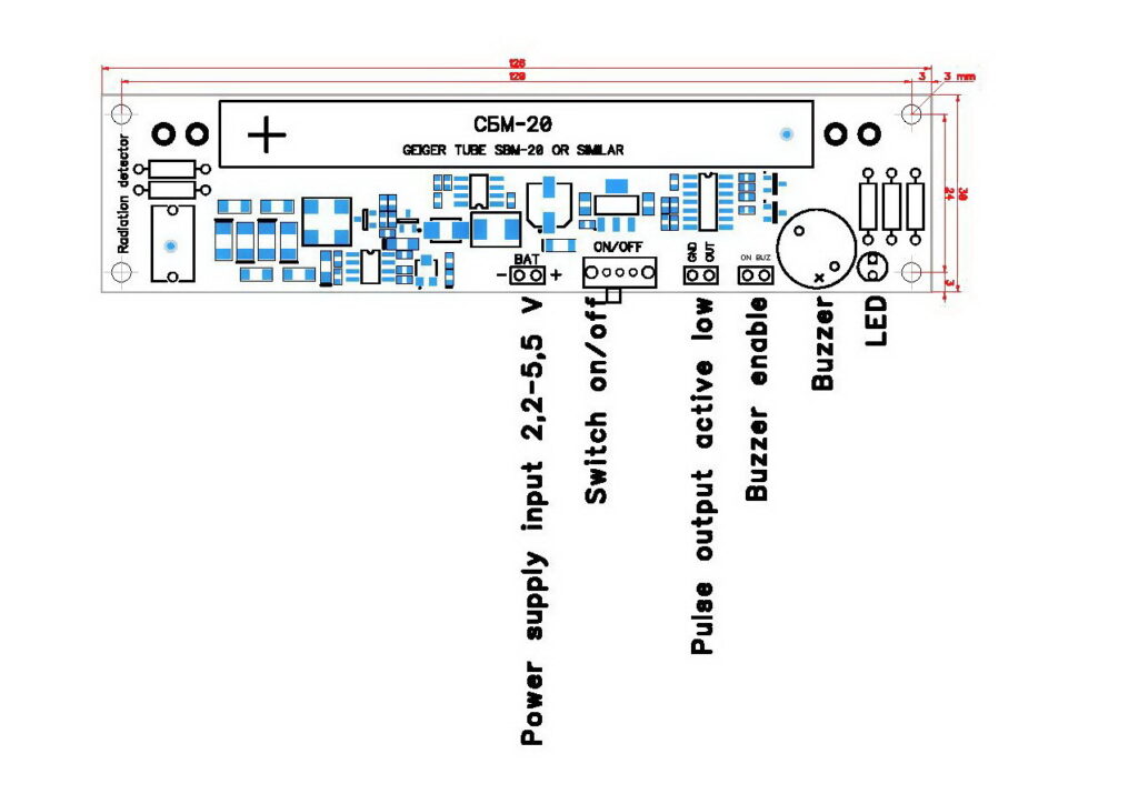
Dimensions and Pin assignments
GGreg20_V3 module pin assignments are as follows:
- BAT – Power supply input 2.2 V – 5.5 V;
- ON. / OFF. – Main switch on/off; / OFF. – switching on / off the main switch;
- OUT – Pulse output, active-low;
- BUZ – Buzzer enable jumper.
The dimensions of the GGreg20_V3 module are as follows:
- X: 126 mm;
- Y: 30 mm;
- Z: 12 mm.
Differences and compatibility with previous versions of GGreg20
| Characteristics | GGreg20_V3 (new version) | GGreg20_V1 | Improvement status |
| Design | monomodular | two-module | improved |
| Calculation formula | – | – | no changes |
| Design and size compatibility | Same, except placing the power switch | – | mostly unchanged |
| Stability of detection results during battery discharge | In the range of 2.4 V – 5.5 V (see note 2 and note 3 ) | Only at 5V supply voltage (μUSB input) | improved |
| Measurement accuracy | 20% | 20% | no change |
| Supply voltage range | 2.2 – 5.5 volts (see note 2 and note 3 ) | 3.7 – 5.5 volts | improved |
| Current consumption | near 35 mA at 5V | near 35 mA at 5V | no change |
| Autonomous power supply | 1 cell Li (3.7V) or 2 cell Ni (2.4V) battery or battery 3V or AC / DC adapter 2.4V – 5.5V (see note 2 and note 3) | 1 cell Li (3.7V) or 3 cell Ni (3.6V) battery or 3 cell battery (4.5V) or AC / DC (5V) adapter | improved |
| User interfaces | LED, buzzer, Output connector | LED, buzzer, Output connector | no change |
| Complexity of the integration | Two connectors and one jumper (total 6 pins) | Three connectors and a jumper (11 pins in total) | simplified |
| Protection against connection errors | Key-protected connectors are used and a Schottky diode is installed (see note 2 and note 3) | Not provided | improved |
Note 1 The GGreg20_V2 module version has not been included in the comparison because it was developed for other design solutions (and did not provide space for the SBM-20 tube on the module board).
Note 2 The module board has a default protection diode against erroneous pole reversal when connecting the battery. Such protection will be appropriate despite the fact that it slightly narrows the voltage range of the input power supply which will be 3-5.5 volts. This narrows the voltage range of the input power supply: 3 – 5.5 volts.
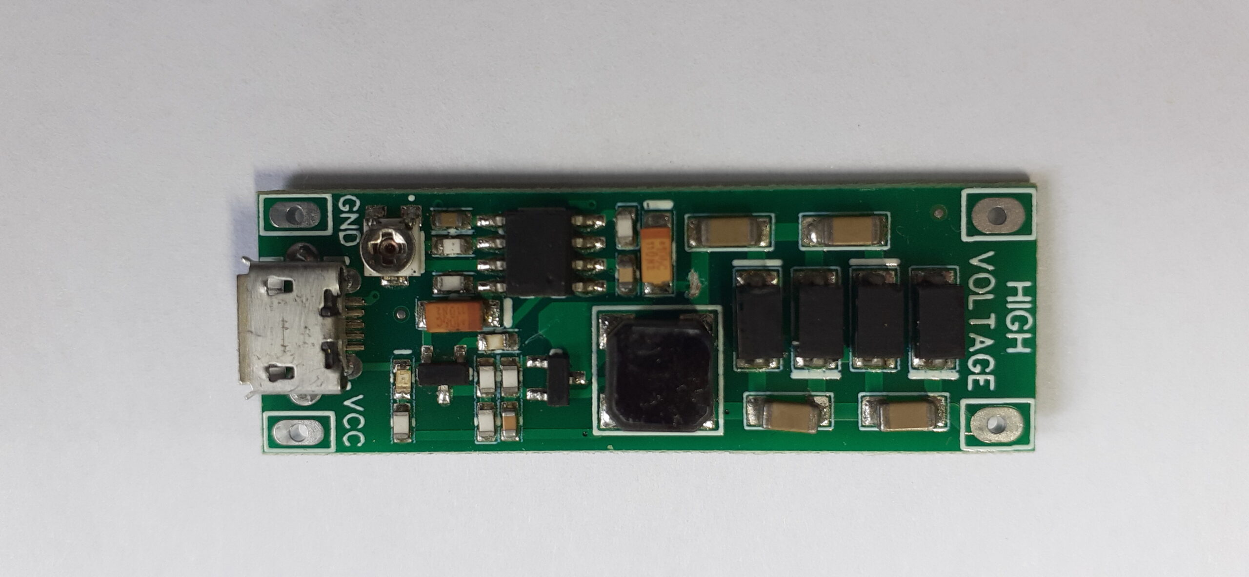
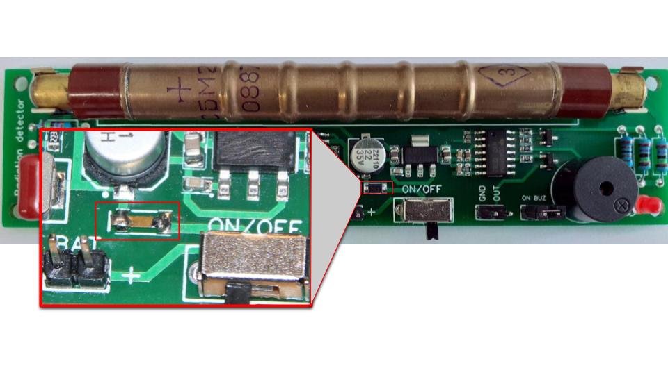
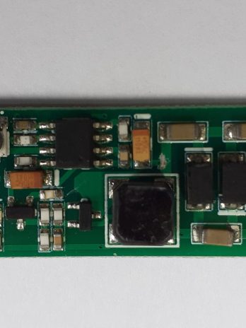
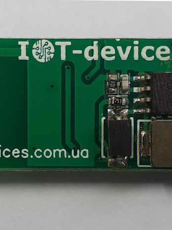
Note 3 If you want to power the GGreg20_V3 from a 2.4 Volt source, you need to short the Schottky diode shown in the figure below with a wire or replace it with a 0 Ohm resistor. Note, however, that such a correction will disable the module’s reverse polarity protection.
Fig. GGreg20_V3 Reverse Polarity Protection Diode Manual Replacement Example
Switching-on and measurements
This module is ready for use. The GGreg20_V3 modules are adjusted, configured, and tested for compliance with the declared technical data before being shipped. Any adjustments or settings made by the customer may damage the module or introduce technical inconsistencies.
Connect the power input from the selected power source.
Turn on the power supply. After 10-15 seconds, you will hear a sound and see light signals when the active particles enter the tube.
At normal background radiation, the tube registers and generates 20-30 pulses per minute. The number of pulses can vary depending on weather or cosmic radiation.
Consider the average number of signals per minute.
If you receive more than 60 signals per minute, be careful: your detector has “felt” a dangerous level of ionizing radiation from the environment or food, mushrooms, wood, etc Your detector has “felt” the effects of ionizing radiation emissions from the ambient environment or food, mushrooms, or wood, etc.
In short, the formula is simple: you need to accumulate the number of ingoing GPIO pulses per minute and then multiply by a factor. Like this:
microsieverts per hour = (pulses per minute) * 0.0092
where 0.0092 is a coefficient obtained from the tube manufacturer’s documentation.
Tubes can vary (+ -20%), so we recommend using a conversion factor of 0.0054 to 0.0092 and calibrating the calculations with a trusted (certified) device.
Note: The differences between the tubes are: conversion factor for J305 is 0.00812, deadtime: 180 microseconds. Drivers and examples for SBM20 are compatible, but require replacement of the specified coefficients. It is recommended to operate the tube in a casing, as its bulb is transparent and measurements may be affected by photons of sunlight and similar factors.
Product kit sets:
1. GGreg20_V3 basic
- GGreg20_V3 Module — 1 pc
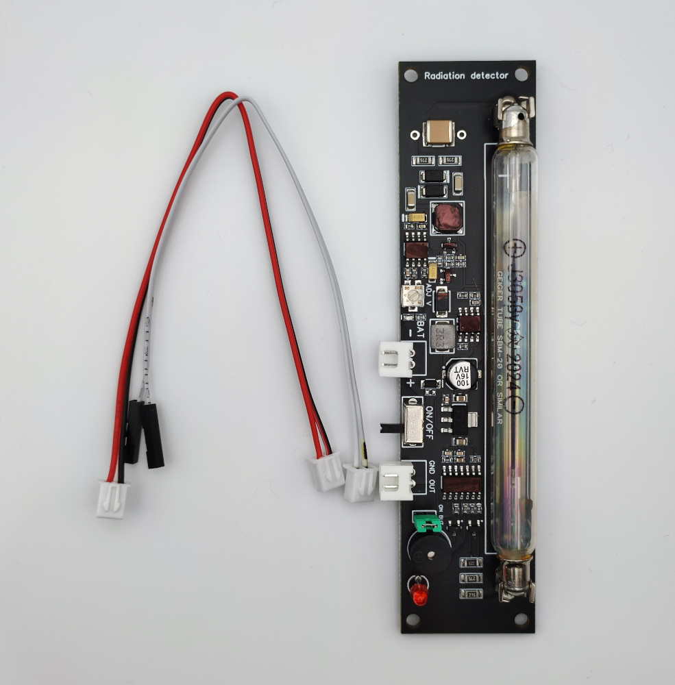
2. GGreg20_V3 basic + Connectors (installed) and cables
- GGreg20_V3 Module — 1 pc
- Connector JST XH 2P male straight — 2 pcs installed on the module board;
- Pulse output cable, 15 cm, with connectors — 1 pc:
- JST XH 2P female on the one hand Dupont 2x1P female on the other hand
- Dupont 2x1P female on the other side
- Power supply input cable, 15 cm, with JST XH 2P female connector on one side — 1 pc
3. GGreg20_V3 basic + SBM-20 tube
- GGreg20_V3 Module — 1 pc
- SBM-20 tube — 1 pc
4. GGreg20_V3 basic + SBM-20 tube + Connectors (installed) and cables
- GGreg20_V3 Module — 1 pc
- SBM-20 tube — 1 pc
- Connector JST XH 2P male straight — 2 pcs installed on the module board;
- Pulse output cable, 15 cm, with connectors — 1 pc:
- JST XH 2P female on one side and
- Dupont 2x1P female on the other side
- Power supply input cable, 15 cm, with JST XH 2P female connector on one side — 1 pc
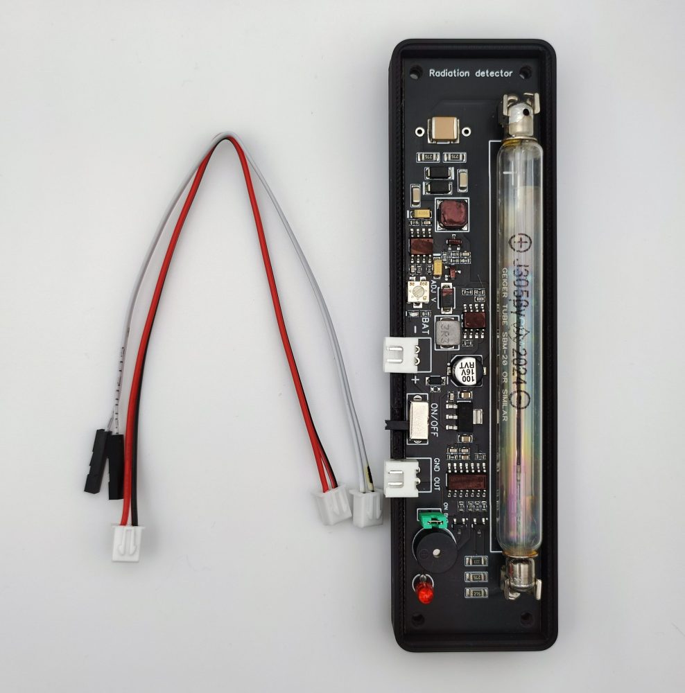
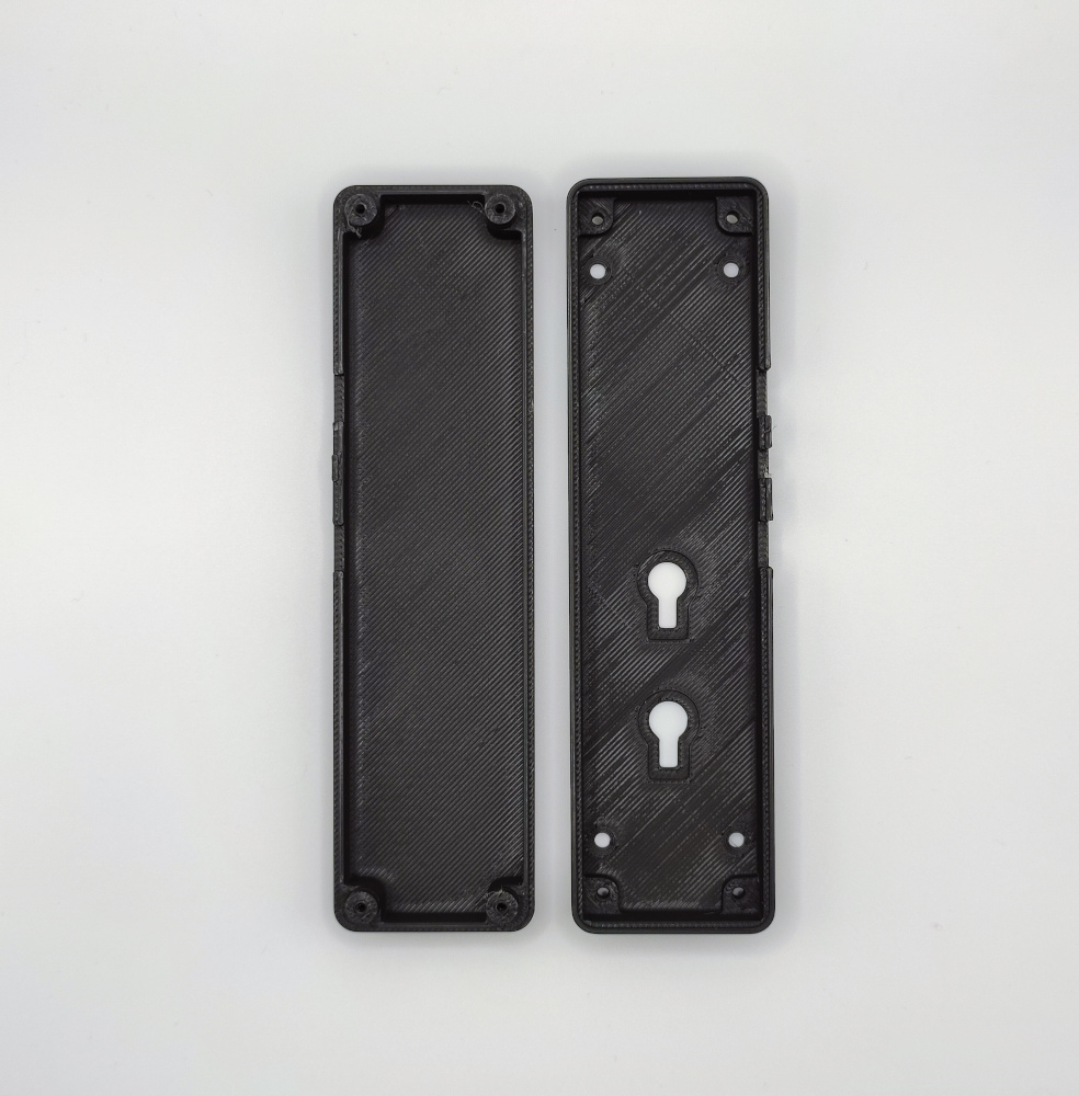
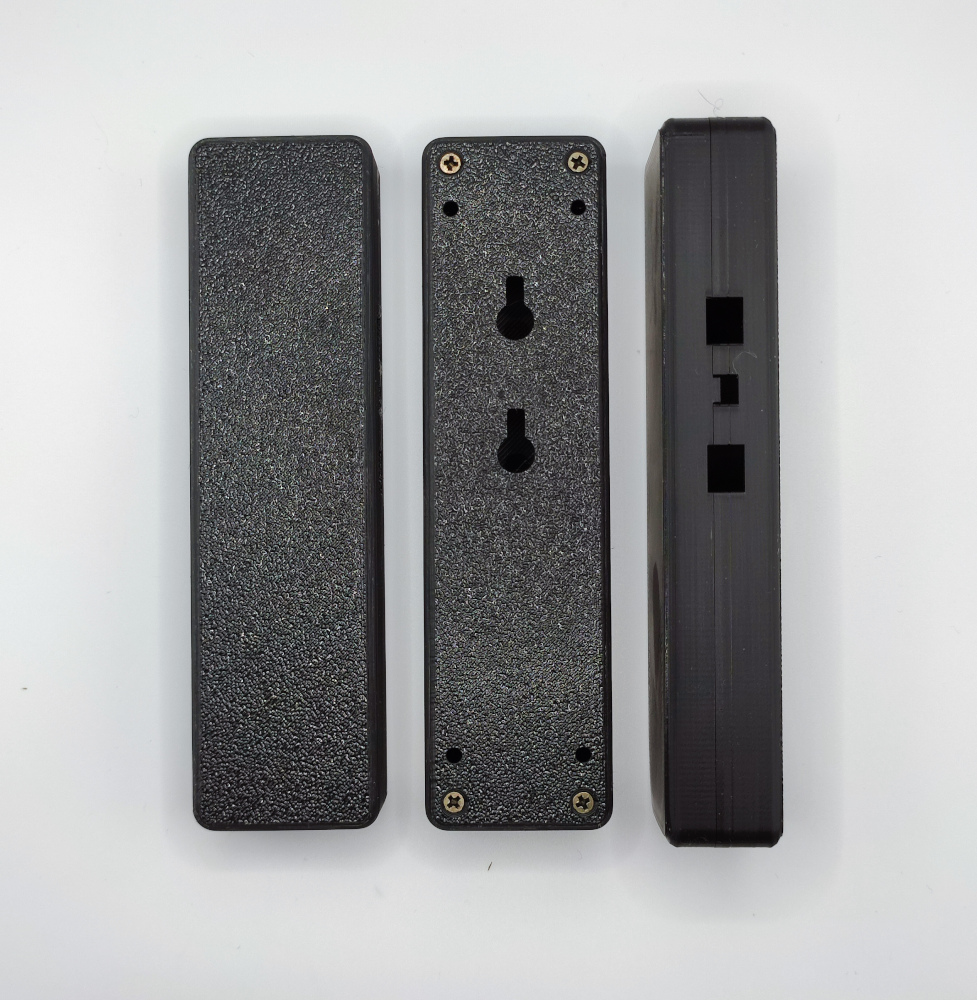
5. GGreg20_V3 basic + Tube SBM-20 + Connectors (installed) and cables + Case(3d printing)
- GGreg20_V3 Module — 1 pc
- SBM-20 tube — 1 pc
- Connector JST XH 2P male straight — 2 pcs installed on the module board;
- Pulse output cable, 15 cm, with connectors — 1 pc:
- JST XH 2P female on one side and
- Dupont 2x1P female on the other side
- Power supply input cable, 15 cm, with JST XH 2P female connector on one side — 1 pc
- Case – 3D printed – 1 pc
6. GGreg20_V3 basic + J305 tube
- GGreg20_V3 Module — 1 pc
- J305 tube — 1 pc
7. GGreg20_V3 basic + J305 tube + Connectors (installed) and cables
- GGreg20_V3 Module — 1 pc
- J305 tube — 1 pc
- Connector JST XH 2P male straight — 2 pcs installed on the module board;
- Pulse output cable, 15 cm, with connectors — 1 pc:
- JST XH 2P female on one side and
- Dupont 2x1P female on the other side
- Power supply input cable, 15 cm, with JST XH 2P female connector on one side — 1 pc
8. GGreg20_V3 basic + J305 tube + Connectors (installed) and cables + Case(3d printing)
- GGreg20_V3 Module — 1 pc
- J305 tube — 1 pc
- Connector JST XH 2P male straight — 2 pcs installed on the module board;
- Pulse output cable, 15 cm, with connectors — 1 pc:
- JST XH 2P female on one side and
- Dupont 2x1P female on the other side
- Power supply input cable, 15 cm, with JST XH 2P female connector on one side — 1 pc
- Case – 3D printed – 1 pc
Technical description: GGreg20_V3 Datasheet ENG 2026, GGreg20_V3 Datasheet UKR
References
|
Manufacturer site |
https://iot-devices.com.ua |
|
Shop for orders |
|
| Tindie Store | |
| https://www.facebook.com/IoT-devices-114746816966582 | |
| https://twitter.com/iotdevicescomua | |
| YouTube | https://www.youtube.com/channel/UCHpPOVVlbbdtYtvLUDt1NZw |
| info@iot-devices.com.ua |
Manufacturer’s notice
Dear Reader! Thank you for your interest in our products. We hope that you enjoy this device. “IoT-devices” has been made possible thanks to the support of our Customers, as well as our experience and love for Electronics.
Designed and manufactured by IoT-devices with freedom and wisdom in Ukraine in 2021. All rights reserved.
12 reviews for Detector of radioactive particles GGreg20_V3 Geiger counter
Only logged in customers who have purchased this product may leave a review.
Related products
-
- Hardware modules, Accessories, Control, Developed and manufactured in Ukraine, Do it yourself
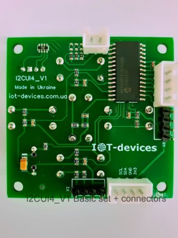
I2CUI4_V1 user interface – I2C module with 5-key keyboard
- 1080грн. 1677.60грн.Price range: 1080грн. through 1677.60грн.
- Select options This product has multiple variants. The options may be chosen on the product page

Donald, Tindie Customer (verified owner) –
Donald | Sept. 14, 2021
Country: Canada
Really well-made and well-documented device!
Excellent build quality and documentation; well-packaged for shipping, too. Looking forward to making an enclosure with battery holder to make it portable!
Ratings Breakdown:
Product: 5.00
Documentation: 5.00
Shipping: 5.00
Communication: 5.00
Source: https://www.tindie.com/stores/iotdev/reviews/?rating=5
Patrick, Tindie Customer (verified owner) –
Patrick | Feb. 12, 2022
Country: Netherlands
Delivers on every promise
This is very well build; the board is clean, well laid out, professionally assembled and it works great.
The detector arrived well protected and thus in one piece (international mail did not get to claim another victim).
Ratings Breakdown:
Product: 5.00
Documentation: 4.00
Shipping: 5.00
Communication: 5.00
Source: https://www.tindie.com/stores/iotdev/reviews/?rating=4
Heinz-Bernd, Tindie Customer (verified owner) –
Heinz-Bernd | Aug. 19, 2022
Country: Germany
Excellent product, fast shipping!
I got the counter w/ SBM-20 tube plus the enclosure and wires, so ready to-go. The enclosure looks great quality and is screwed together. The counter works great. What amazes me is the fast shipping. Delivery from Ukraine (despite all the challenges at the moment, to put it mildly) to Germany was much faster than deliveries I get from the USA.
Ratings Breakdown:
Product: 5.00
Documentation: 5.00
Shipping: 5.00
Communication: 5.00
I can 100% recommend this product and vendor.
Source: https://www.tindie.com/stores/iotdev/reviews/?rating=5
aldweb, Etsy Customer (verified owner) –
aldweb on Sep 19, 2024
Country: France
aldweb added a photo of their purchase: Link
5 out of 5 stars
Wonderful contact with the seller, they are doing a great job in Kyiv. Support Ukraine!
Source: https://www.etsy.com/shop/iotdevicesllc?ref=seller-platform-mcnav#reviews
Ihor, Etsy Customer (verified owner) –
Ihor on Mar 26, 2024
Country: USA
5 out of 5 stars
It’s one of the items you don’t think of having at home but it can be used for more than just educational purposes. There are certain areas in this country where it’s nice to have it if you hiking, getting vegetables, firewood or just wanted to check that old item you bought in a thrift shop. We often put old items in our home without knowing where did they come from. Since I like to work with electronics I got one and it’s very good. Easy to build projects with and integrate into smart home. Highly recommend.
Source: https://www.etsy.com/shop/iotdevicesllc?ref=seller-platform-mcnav#reviews
Stephane, Etsy Customer (verified owner) –
Stephane on Dec 11, 2023
Country: France
5 out of 5 stars
Arrived in packaging that protects the product very well!
Source: https://www.etsy.com/shop/iotdevicesllc?ref=seller-platform-mcnav#reviews
Hanna B, Trustpilot Review (verified owner) –
Hanna B Nov 6, 2023
Country: GB
Rated 5 out of 5 stars
I ordered the Greg20_V3 geiger counter here. Excellent, well-documented product, fast delivery, and really responsive and helpful support. Highly recommended!
Date of experience: October 22, 2023
Source: https://www.trustpilot.com/reviews/6547f4dcae23bde6b691c282
CD, Trustpilot Review (verified owner) –
CD Apr 24, 2024
2 reviews
Country: US
Rated 5 out of 5 stars
IoT-devices was great. Awesome customer support, answered my questions quickly, and their geiger counter is really nice and well constructed and works really well. You can use it as is,or interface it to your own devices.
Date of experience: April 19, 2024
Source: https://www.trustpilot.com/reviews/6628f4cf0ea663dbfcb5f5f0
LD, Trustpilot Review (verified owner) –
LD Sep 24, 2024
3 reviews
Country: FR
Rated 5 out of 5 stars
Best DIY Geiger Counter with awesome documentation and support
I have been running two Greg20_V3 geiger counters modules from IoT-devices since two years.
I bought two more of these modules recently.
These DIY Geiger modules are great and easy to interface with an ESP32 microcontroler.
International delivery is surprisingly working well from Kyiv (Ukraine), even though a little slow of course.
Customer service is outstanding.
Support Ukraine!
Date of experience: September 16, 2024
Source: https://www.trustpilot.com/reviews/66f2cc2367a94de218a4877a
Pavlo, Trustpilot Review (verified owner) –
Pavlo, Feb 06, 2025
2 reviews
Country: EG
Rated 5 out of 5 stars
Verified
Excellent idea.
Date of experience: January 09, 2025
Source: https://www.trustpilot.com/reviews/67a4e14dc2f7cf5c2f217cd6
John, Trustpilot Review (verified owner) –
John, February 10, 2025
3 reviews
Country: GB
Rated 5 out of 5 stars
Verified buyer
Configuration: GGreg20_V3 Basic + J305 tube
Thank you, everything is fine
Nice module, arrived in good time and works well.
Date of experience: January 6, 2025
Source: https://www.trustpilot.com/reviews/67aa7a3ba64ece4aaf521bf4
David, Trustpilot Review (verified owner) –
David, February 3, 2025
1 reviews
Country: AU
Rated 5 out of 5 stars
Verified buyer
Configuration: GGreg20_V3 Basic
Great Experience.
My order was processed and shipped quickly. Delivery was very reasonable seeing I am on ther opposite side of the earth.
Very happy with my purchase and now adds another environmental sensor I can monitor.
Thank you.
Date of experience: January 25, 2025
Source:https://www.trustpilot.com/reviews/67bad845b4664cc76c7934a0