

I2CUI4_V1 user interface – I2C module with 5-key keyboard
1080грн. 1677.60грн.Price range: 1080грн. through 1677.60грн.
I2CUI4_V1 module – user Interface I2C keypad with 5-keys, RGB-LED and buzzer for on premise IoT device management.
Compatible with ARDUINO, ESP12.OLED_V1 controllers, NodeMCU board (based on ESP8266-12), modules on the ESP8266EX, ESP32 or other chip, which are powered by a voltage in the range from 1.8 to 5.5 V.
Functionality
The module connects to the main controller via a 4-wire I2C bus interface and provides the following functions:
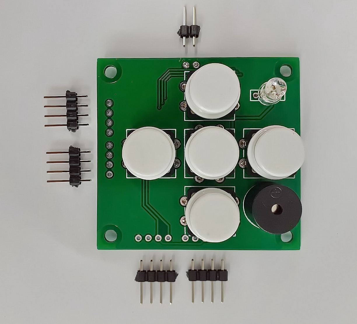
- Data entry with a five-button keyboard (left, right, down, up, OK)
- Data output to RGB LED;
- Output of sound sequences to the active indicator of the buzzer type;
- I2C bus input and output through ports. Input for connection to MCU and output – for connection of any external devices that support the I2C specification.
Thanks to the use of the I2C bus and the MCP23017 port expander, GPIO savings of the main controller and the ability to input and output information in a user-friendly way are achieved. The rest of 7 GPIOs are connected to separate pin connectors for additional I / O signals connection according to the user’s design.
Description
I2CUI4_V1 module – user Interface I2C keypad with 5-keys, RGB-LED and buzzer for on premise IoT device management.
Compatible with ARDUINO, ESP12.OLED_V1 controllers, NodeMCU board (based on ESP8266-12), modules on the ESP8266EX, ESP32 or other chip, which are powered by a voltage in the range from 1.8 to 5.5 V.
Functionality
The module connects to the main controller via a 4-wire I2C bus interface and provides the following functions:
- Data entry with a five-button keyboard (left, right, down, up, OK)
- Data output to RGB LED;
- Output of sound sequences to the active indicator of the buzzer type;
- I2C bus input and output through ports. Input for connection to MCU and output – for connection of any external devices that support the I2C specification.
Thanks to the use of the I2C bus and the MCP23017 port expander, GPIO savings of the main controller and the ability to input and output information in a user-friendly way are achieved. The rest of 7 GPIOs are connected to separate pin connectors for additional I / O signals connection according to the user’s design.
Int A & Int B output signals are available – can be used for interrupt processing when the state of the module inputs changes.
Application
I2CUI4_V1 will be convenient to use as a control panel and status display in user devices:
- electronic clocks,
- radiation level dosimeters,
- smart outlets,
- thermostats,
- multimedia and audio devices,
- weather stations and others.
Compatibility
Compatible with controllers and platforms:
- ARDUINO,
- ESP12.OLED_V1,
- NodeMCU board (based on ESP8266-12),
- modules on the ESP8266EX chip,
- ESP32,
- or others powered by 1.8 – 5.5 V;
- integration into Home Assistant (with ESP Home plugin), Blynk, OpenHab, Node-RED, Tasmota is possible.
Minor and major versions of the module
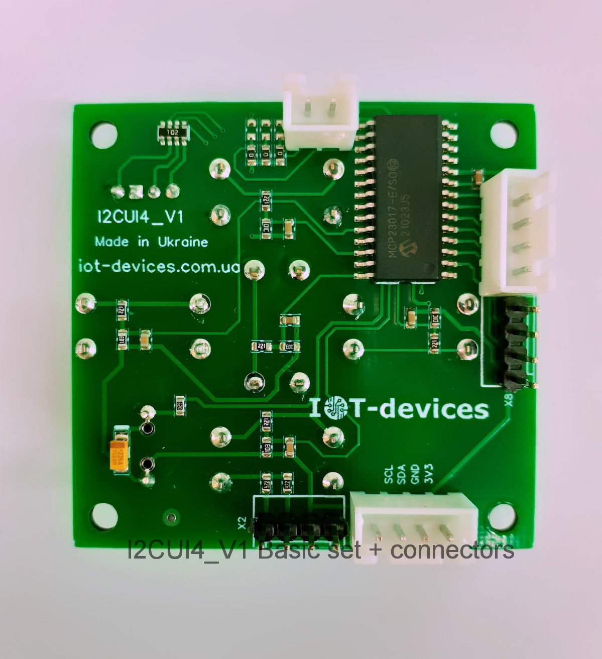
Unlike the minor version I2CUI3_V1, the I2CUI4_V1 user interface module uses a widely supported 16-bit MCP23017 port expander. This makes it possible to use this module in devices for integration into Home Assistant, Arduino and many others.
Chips of user interface modules:
- I2CUI3_V1 – 8-bit, I2C, PCA9538, 2^3 GPIOs;
- I2CUI4_V1 – 16-bit, I2C, MCP23017, 2^4 GPIOs.
The major version of I2CUI4_V1 has the following features:
- single digital interface – 2 x I2C (input / output) ports;
- 5 “joystick” buttons; sound indicator; RGB LED indicator;
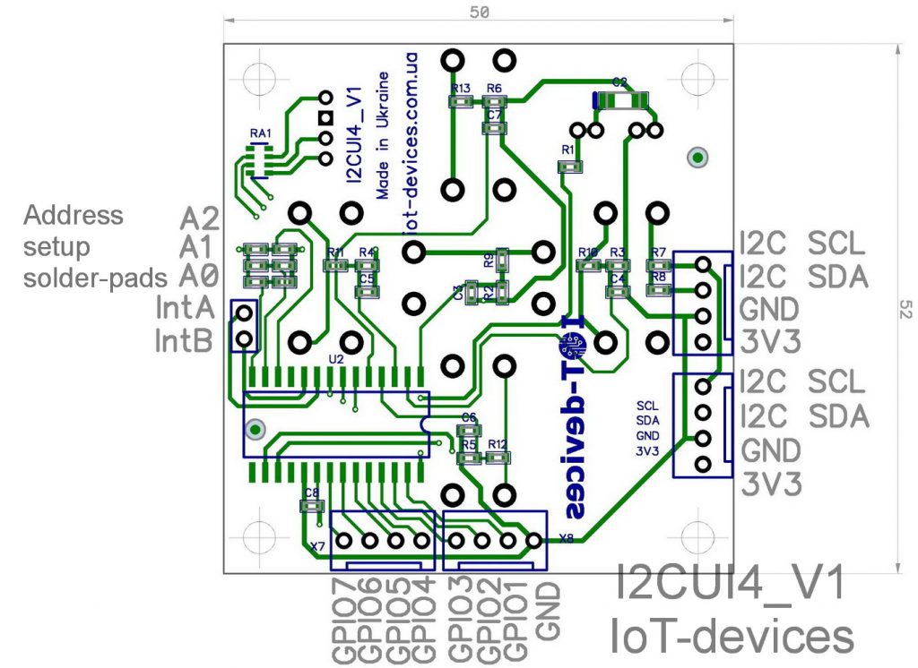
- selection of one of 8 module addresses on the I2C bus via solred-pads;
- 7 free GPIOs are connected to separate pin connectors.
Driver-level support
Support for the MCP23017 chip at the driver level is stated in particular by the following platforms:
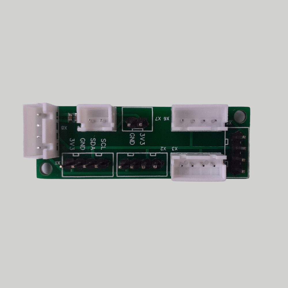
Assignment of module ports
| Port Name | Purpose | Logic |
| GPIO 0 (GPB0) | Buzzer on board | 3V3 or 5V active high |
| GPIO 1 (GPB1) | Free, for user extensions | 3V3 or 5V active low |
| GPIO 2 (GPB2) | Free, for user extensions | 3V3 or 5V active low |
| GPIO 3 (GPB3) | Free, for user extensions | 3V3 or 5V active low |
| GPIO 4 (GPB4) | Free, for user extensions | 3V3 or 5V active low |
| GPIO 5 (GPB5) | Free, for user extensions | 3V3 or 5V active low |
| GPIO 6 (GPB6) | Free, for user extensions | 3V3 or 5V active low |
| GPIO 7 (GPB7) | Free, for user extensions | 3V3 or 5V active low |
| GPIO 8 (GPA0) | LED – Red on board | 3V3 or 5V active high |
| GPIO 9 (GPA1) | LED – Green on board | 3V3 or 5V active high |
| GPIO 10 (GPA2) | LED – Blue on board | 3V3 or 5V active high |
| GPIO 11 (GPA3) | Key Up on board | 3V3 or 5V active high |
| GPIO 12 (GPA4) | Key Down on board | 3V3 or 5V active high |
| GPIO 13 (GPA5) | Key Left on board | 3V3 or 5V active high |
| GPIO 14 (GPA6) | Key Right on board | 3V3 or 5V active high |
| GPIO 15 (GPA7) | Key OK on board | 3V3 or 5V active high |
| A0 | I2C address bit 0 | GND=0; VDD=1, by default 0 |
| A1 | I2C address bit 1 | GND=0; VDD=1, by default 0 |
| A2 | I2C address bit 2 | GND=0; VDD=1, by default 0 |
| IntA | Interrupt for GPIO group A | 3V3 or 5V active low |
| IntB | Interrupt for GPIO group B | 3V3 or 5V active low |
| I2C SDA | I2C I/O | 3V3 or 5V active low |
| I2C SCL | I2C I/O | 3V3 or 5V active low |
| 3V3 | Power | 1.8-5.5 V |
| GND | Common ground |
Power supply and consumption
Power supply of the module is possible in the range of voltages of 1,8 – 5,5 volts. The current consumption of the I2CUI4 module at rest is about 1 microampere. In the case of simultaneous data output to R + G + B + buzzer, the maximum current consumption can reach 20 milliamperes.
Addressing on the I2C bus
The address of the module has a fixed and variable part:
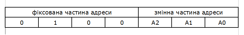
The address of the module I2CUI4_V1 is selected in accordance with the documentation on the chip MCP23017, because it is this chip of the module that interacts with the main controller via the I2C bus.
Interrupt handling
The module has two interrupt channels: Int A and Int B. All processing and logic (active-low) corresponds to the documentation for the MCP23017 chip. Interrupt processing is provided for the master controller to monitor changes in GPIO states set to input mode.
According to the design of the interface module I2CUI4_V1, input mode:
- must be set for:
- GPIO 11 (GPA3) – Key Up on board
- GPIO 12 (GPA4) – Key Down on board
- GPIO 13 (GPA5) – Key Left on board
- GPIO 14 (GPA6) – Key Right on board
- GPIO 15 (GPA7) – Key OK on board
- can be set for spare GPIO ports if used by the user as inputs: GPIO 1 (GPB1), GPIO 2 (GPB2), GPIO 3 (GPB3), GPIO 4 (GPB4), GPIO 5 (GPB5), GPIO 6 (GPB6) ), GPIO 7 (GPB7).
Ports GPIO 0 (GPB0) Buzzer on board, GPIO 8 (GPA0) LED – Blue on board, GPIO 9 (GPA1) LED – Green on board, GPIO 10 (GPA2) LED – Red on board – work on the module as outputs.
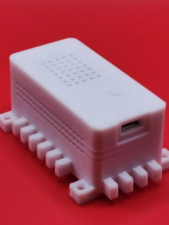
Module dimensions
- Dimensions of the module board 50 x 52 mm,
- Module height (Z): 15 mm.
Product kit sets
The module is delivered in the following sets:
- Basic set:
- 1 pc – I2CUI4_V1 user interface module;
- PCB Headers ( Dupont Headers ) 2,54 20p – 1 pc.
- Basic + Connectors set: (Note: The user receives the module with installed connectors )
- 1 pc – Basic set;
- Connectors:
- JST XH 2,54 2p – 1 pc:
- JST XH 2,54 4p – 4 pcs..
- Basic + Connectors + Cables set: (Note: The user receives a module with installed connectors )
- 1 pc – Basic + Connectors set;
- Cables:
- JST XH 2,54 4p – JST XH 2,54 4p – 1 pc.
- JST XH 2,54 2p – JST XH 2,54 2p – 1 pc.
- JST XH 2,54 4p – Dupont 4p – 1 pc.
- JST XH 2,54 2p – Dupont 2p – 1 pc.
Technical description: i2cui4_v1-product-description-ukr, i2cui4_v1-product-description-eng.
References
| Manufacturer site | https://iot-devices.com.ua |
| Shop on Tindie for international orders | https://www.tindie.com/stores/iotdev/ |
| Shop for local orders within Ukraine | https://iot-devices.com.ua/shop/ |
| Facebook page | https://www.facebook.com/IoT-devices-114746816966582 |
| https://twitter.com/iotdevicescomua | |
| YouTube | https://www.youtube.com/channel/UCHpPOVVlbbdtYtvLUDt1NZw |
| info@iot-devices.com.ua |
The port expander chip used in the module:
| Microchip MCP23017 16-Bit I2C I/O Expander with Serial Interface |
https://www.microchip.com/wwwproducts/en/mcp23017 |
Manufacturer message
Dear Reader! Thank you for your interest in our products. We hope that you enjoy this device. IoT-devices was born thanks to the support of our customers and thanks to our experience and love for Electronics.
Designed and made by IoT-devices with freedom & wisdom in Ukraine – 2021. All rights reserved.
Additional information
| Weight | 0.2 kg |
|---|
Only logged in customers who have purchased this product may leave a review.
Related products
-
- Hardware modules, Developed and manufactured in Ukraine, Do it yourself, Sensors
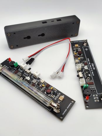
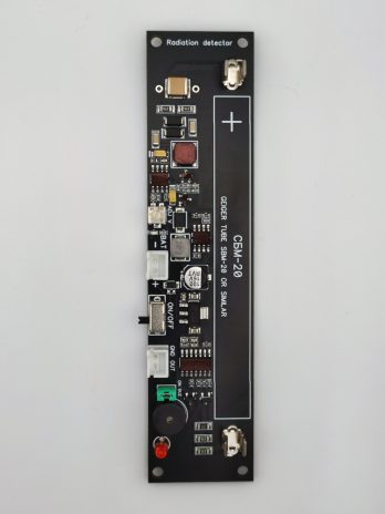
Detector of radioactive particles GGreg20_V3 Geiger counter
- 1729.35грн. 3760.20грн.Price range: 1729.35грн. through 3760.20грн.
- Select options This product has multiple variants. The options may be chosen on the product page
Reviews
There are no reviews yet.