Description of the problem
We have a main system controller and several devices with an I2C interface that need to be connected to it. The figure shows an approximate classic set of modules that may need to be connected to the main controller (MCU).
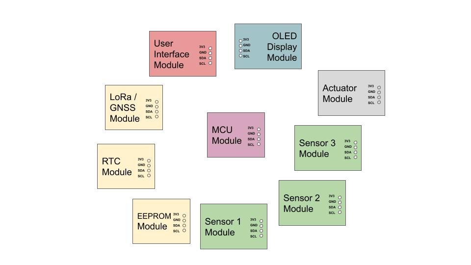 |
| Pic. Various I2C Modules Example |
Most microcontrollers (MCUs) are miniature devices and have a very limited budget for free I / O ports. Typically, on Arduino / ESP8266 / ESP32 / STM32 controllers, only one interface can be reserved for the I2C bus (even if there are two) – two GPIO ports for SDA and SCL signal channels.
There are at least two reasons for this.
First, GPIO ports are a valuable resource on the main controller. They are involved in no less important external interfaces – UART, SPI, Deep Sleep Wakeup, sub-button inputs, actuator outputs (s), etc.
Second, the design of the main controller module board must take into account the size limitations: the more connectors installed on this board, the greater the linear dimensions it will have.
Note. We also know that the I2C serial bus can be implemented not only in hardware, with fixed I / O ports on the MCU, but also in software, when the bus signal lines can be assigned to any MCU’s GPIO ports. Moreover, the software implementation of the bus allows to declare multiple I2C software buses with different Bus_ID.
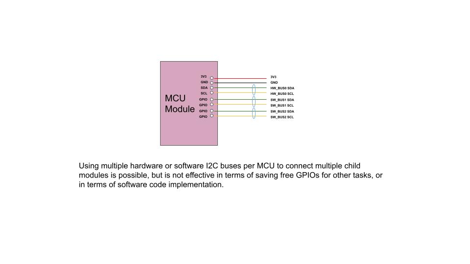 |
| Pic. MCU I2C bus hardware and software implementations |
But the manifestation of several I2C software buses simultaneously within one MCU reduces the number of free pins for other tasks. Because of this, such opportunities are rarely used. Exceptions to this may be situations when such a technique avoids problems that cannot be solved in any other way. For example, addressing collisions (two different devices with the same 7-bit address) and similar problems. But even for such problems, it is more efficient to use an I2C hardware multiplexer than multiple I2C software buses.
Problem solution
To solve the problem of one I2C port on the MCU, the hardware I2C bus interface splitter is most often used. It is a passive hub that splits one existing I2C interface into the required number of the same interfaces.
There are many similar devices on the market, but we will give an example of a device of our own production – I2CHUB_V1, which has 6 I2C ports: 3 x 4 pin JST HX2.54, 3 x 4 pin Dupont and two additional dedicated “bidirectional” 2 pin power ports.
 |
| Pic. I2C bus interface splitter – I2CHUB_V1 as an example |
Another way to solve the problem in the case of a bus-type serial interface, such as I2C, maybe to use predefined end-to-end interfaces in individual sensor modules or actuators that connect to the bus. See the picture below as an example of such sensor-module boards.
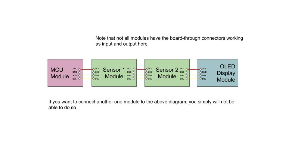 |
| Pic. Not widespread In-Out (two-connector) I2C sensor modules connection example |
The “input” interface of each such module is connected to the MCU or the previous sensor module on the bus, and the “output” interface allows you to cascade the next module. Some manufacturers provide two I2C bus interfaces for this purpose. But, unfortunately, most modules are not equipped with such capabilities. – Therefore, we consider I2C HUB as a more common and universal approach. Below you will find the basic schemes for module connection with the use of the hub.
Note. As the number of connections increases: ,
– it exponentially increasesnumber of failure points (PoF, Point of Failure);
– the risk of human error when making interface signal connections.
For the protection of equipment from failure and installation errors, in order to increase the overall reliability of the system, we recommend:
- to use connectors with a safety key as often as possible;
- to use modules with mutually compatible electrical interfaces and physical connectors.
While we recommend using key connectors whenever possible, we also try to take into account the realities of the electronic components market and meet the needs of consumers. That’s why we’ve given the I2CHUB_V1 splitter the ability to act as a type connector converter from JST to Dupont and vice versa.
We consider this a very useful feature, because thanks to the ability of freely reversing JST – Dupont interface cables from one side to the other, the user can connect almost any existing I2C interface modules to the hub. The user can also freely use his own Dupont – Dupont cables.
For the “Order with cables” option in the module I2CHUB_V1 connectors are always soldered in the same way: half of them are 2.54 mm JST connectors (with key), the other half are Dupont pin connectors. This is done to ensure the above-mentioned flexibility of interconnection of various I2C modules.
Schemes of modular connection to the interface splitter
Star
The most common scheme is when all modules are connected to the divider by I2C interfaces. Let’s call it “The Star”.
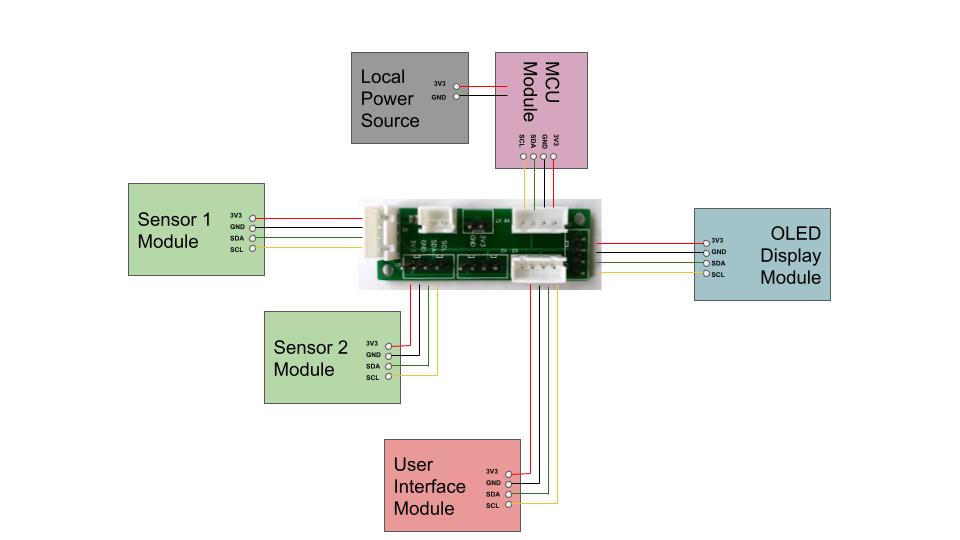 |
| Pic. “The Star” module connection example |
Cascading
The next topology is a cascade of two or more “Stars”, Let’s call it “Cascading”.
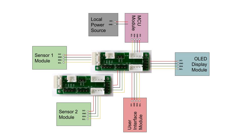 |
| Pic. “Cascading” module connection example |
Because one of the interface splitter ports is always used as an “input”, there may be a lack of free splitter ports in some situations. In this case, the necessary number of splitters is cascaded to provide the desired number of interface ports on the I2C bus.
For example, “IoT-devices”‘s I2CHUB_V1 has 6 I2C ports. If it is planned to connect more than 5 slave devices to MCU in the project, it is possible to cascade two splitters and distribute the corresponding slave devices between their interfaces.
Long Line
The last possible implementation scheme to be included in this publication is a topology with a long data line and two remote independent sources of power. Let’s call it “Long Line”.
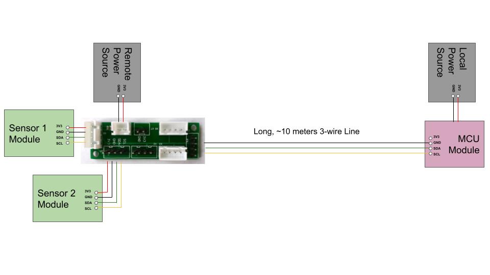 |
| Pic. “Long line” connection with remote power source example |
In this scheme, only three signal lines are used, while the power for the devices comes from a local, independent source on each side. This arrangement allows a relatively long data line to be organized on the I2C serial bus interface without the use of special bus repeaters/amplifiers.
Compatibility of splitters with other systems
If you use modules with different supply voltages in one project, you should pay special attention to the signal matching of such components.
But if you choose to apply a passive splitter that has no conversion or voltage leveling elements just take into consideration that the voltage that you apply to the splitter connectors will reach all the modules connected to the splitter via the respective I2C bus signaling lines.
However, since the classical I2C splitter (such as I2CHUB_V1) is a passive device and does not change the voltage level, it is automatically compatible with any controller you choose to connect it to: Arduino, STM32, ESP8266, ESP32, Raspberry Pi, etc.
Caution: Only you decide which logical levels the components of the project should work with: 1.8V, 3.3V or 5V.
Detailed I2C bus specifications
To view details of all I2C bus features, we recommend reading the official guidelines and specs here:
https://www.nxp.com/docs/en/user-guide/UM10204.pdf
That’s all we planned to tell in this publication. We have considered the features and connectivity of the slave modules to the I2C bus interface of the main controller. We have also shown the main application patterns of the splitter, such as Star, Cascading, Long Line, with the possibility of remote independent powering of individual bus chunks, thanks to the special power “input/output” ports in the splitter.
Thank you for your attention. Ask questions on our social networks.
We wish you success!